V8BoatBuilder
Transplanted Bostonian
- Joined
- November 4, 2002
- Messages
- 3,411
- Reaction score
- 8
- City, State
- East Brunswick, NJ
- Year, Model & Trim Level
- 97 Mountaineer V8 4x4
Introduction
I spent the past weekend installing a new set of Tech Performance and Engineering's Torque Monster Headers on my Mountaineer. This post and thread will evolve over the next few days as a photo-documented "how-to" guide on installation of the headers, and a subsequent review of how they fit and how the performance of the Mountaineer has been increased. I will be editing this first post as the installation guide, the second post will the review. After that, let the comments begin!
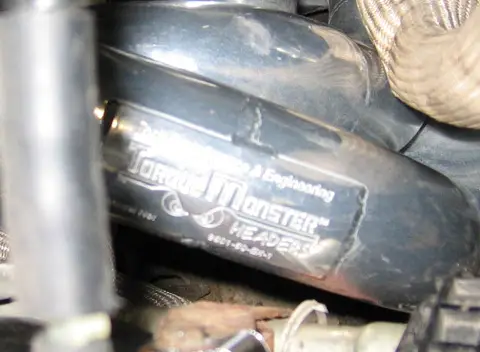
Welded on TP&E logo, pass side header
Why Headers?
I had the stock manifolds out of the truck last June for my valve-job and head gasket repair (see: http://www.explorerforum.com/forums/showthread.php?t=108712 ) and could not believe how restrictive the design was. I had wanted headers at that point, but they were impossible to find. I am also always looking for bolt-on performance mods to increase the V8's power and/or gas mileage. While a supercharger may be the "ultimate" bolt on, bolting one on a 8 year old, 125k mile engine isn't the greatest recipe for reliability. A cam swap would mean discharging the A/C and substantial downtime. Headers on the otherhand, can be bolted on in a weekend, will increase power, and will not harm reliability. They are also a part that can be grown into, should I decide to cam or supercharge down the road (and would be a necessity anyway with said mods.)
Although the FMS headers were just re-released, they are very close in design to the stock manifolds, while the new Torque Monster headers are a much cooler design, with some neat technology behind them.
Tools Requied
Besides the usual compliment of wrenches, a few speciaity tools are needed. Don't make emergency parts runs like I did!
- A copious amount of 3/8" socket extensions and a good u-joint.
- 1/4" to 3/8" and 3/8" to 1/2" socket adapters.
- A good torque wrench.
- An 18mm offset wrench, for tightening the engine mount nuts.
Installation
(You'll have to excuse the salt, dirt, and surface rust. The weather has been really bad up here in Boston latley. Stay tuned for the big underbody painting thread come springtime.)
1) Jack up the truck, and support the lower a-arms or frame on jackstands. Remove wheels and fenderwell linings.
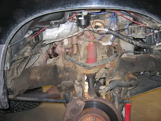
Passenger side fenderwell removed
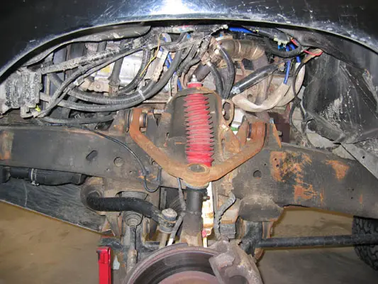
Driver's side fenderwell removed
2) Remove the 13mm bolt that connects the steering shaft. This will allow the lower section of the shaft to be rotated out of the way during installation.
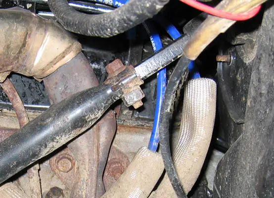
Steering shaft bolt
3) Remove all ignition wires and sparkplugs. Take the wires, and any mounting brackets completely off the engine. You'll be re-routing them once the headers are installed.
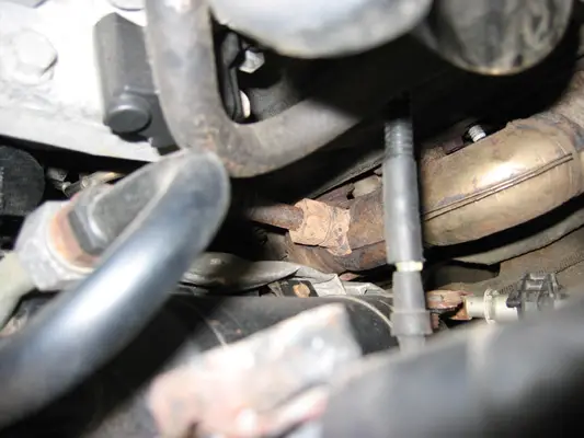
4) Remove manifold to downpipe bolts. There are two per manifold, and can be a pain to reach. U-joints and long extensions are a must.
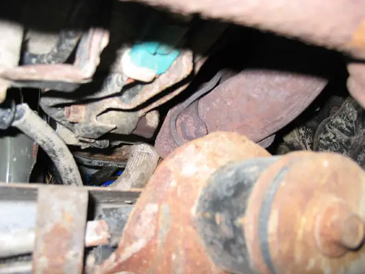
Driver's side downpipe to manifold bolts. View looking up, camera placed next to front driveshaft.
5) Begin to remove the driver's side exhaust manifold to head bolts. Some are studs, some are nuts. The dipstick, bolted onto cylinder seven's aft stud, just pulls straight out from its hole in the block.
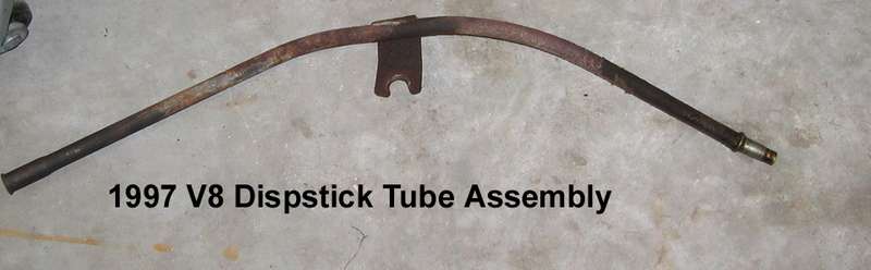
Dipstick assembly
6) Remove the driver's side exhaust manifold. With the steering shaft pointing vertical, it will wiggle out underneith the brake booster.
Removing the driver's side exhaust manifold, side view
Top View
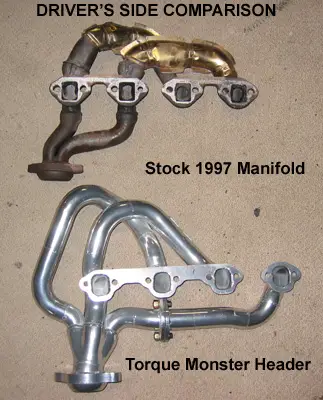
7) With the manifold removed - compare it to the new header. My jaw dropped.")
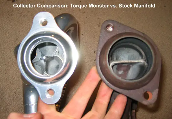
Collector Compasion, stock stamped vs. TM Modified Merge
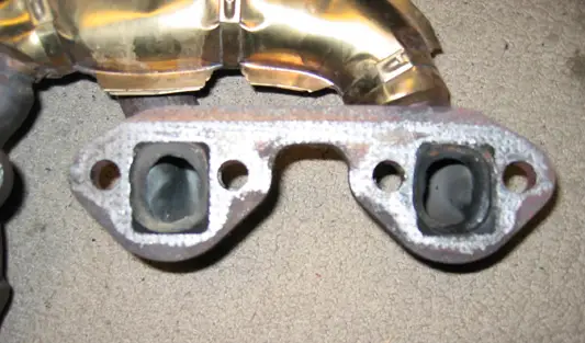
Stock header
Torque Monster Ports
Driver's side manifold removed
8) Install driver's side header. The header comes in two parts, allowing easier installation around the steering shaft and fuel lines.
a. sperate the #5 cylinde tube from the header.
b. Insert the main header piece at the rear of the motor.
c. Drop in the #5 cylinder connector.
d. put one bolt in each header peice, then bolt the two together. It is important to loosely bolt the headers to the head before bolting the flange together.
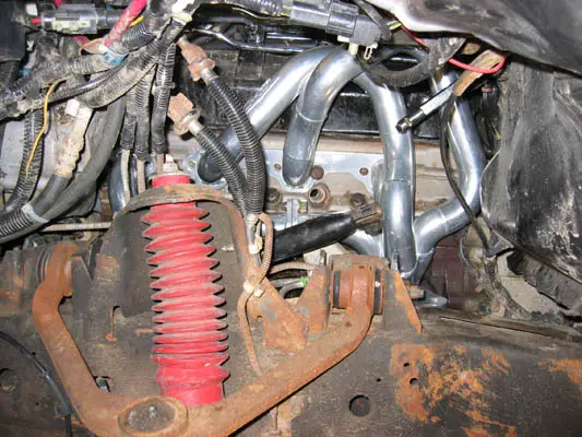
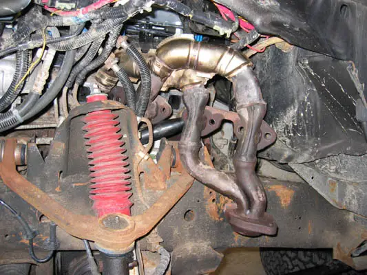
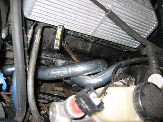
Completed driver's side header
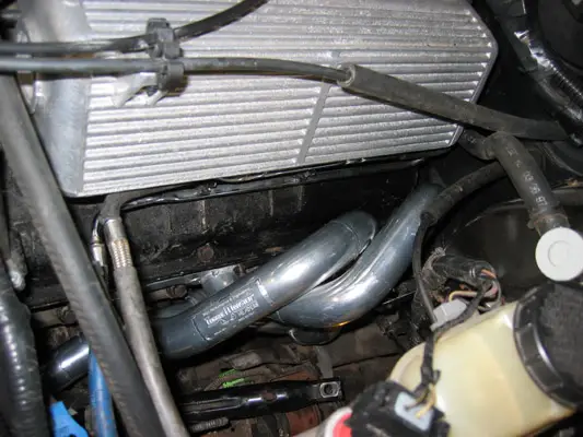
Driver's side Torque Monster Header top view
9) Re-attach dipstick. It will just press into fit, and then can be bolted down with the other 8 header bolts. Normally, a threaded stud will hold the header to the block, and the dipstick will be bolted speratly to the stud. However, the header tube is so close to the stud, the larger nut will not fit on. My dipstick is temporarily bolted below the stud's main nut, untill a smaller nut can be obtained.
Dipstick re-installed
Dipstick top view
10) Torque down all 8 header to head bolts, and the two flange connection bolts. Do NOT connect the header to the downpipe at this point, flexibility is needed when the motor is subsequently lifted from its passenger side mount.
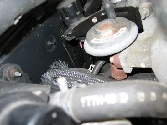
11) Begin to disassemble the passenger side for header installation. Disconnect the MAF, IAT, and crankcase breather from the air intake tube, then remove the intake tube. Remove the air filter and MAF. Lastly, unbolt the bracket that supports the MAF/airbox and the foglight realy. Put it aside, there is no need to remove the foglight relay.

MAF support bracket. I have re-located the climate control vacuum reserve sphere to the upper fender, rather than have it be attached to the fenderwell lining. This 'mini-mod' was done last year during my aux trans filter install.
12) Remove the lower EGR tube-to-manifold connection. I used an adjustible wrench, as none of my combination wrenchs were large enough. Your miliage may vary.
Lower EGR tube-to-manifold nut
13) Remove the EGR vacuum hoses and the upper EGR nut.
Upper EGR nut
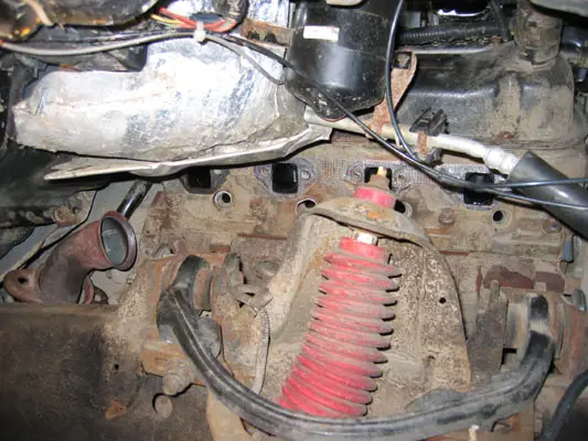
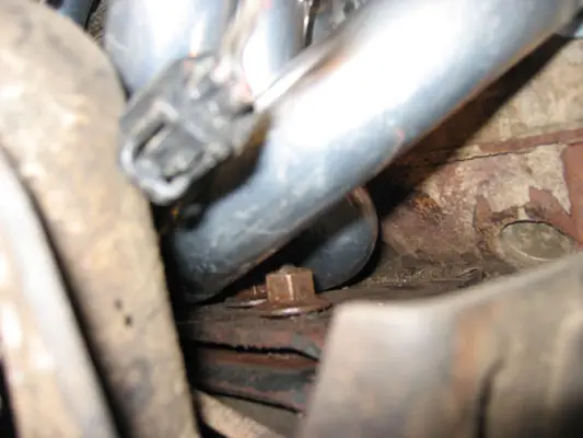
14) Remove the passenger side manifold-to-downpipe connection. I have liberally applied PB-Blaster to the bolt threads.
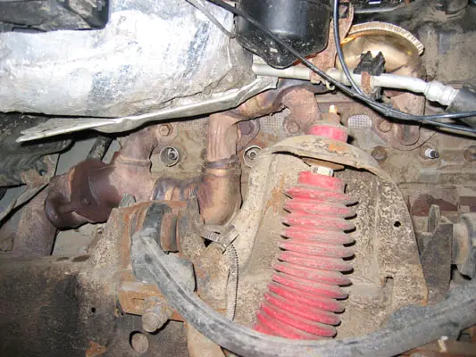
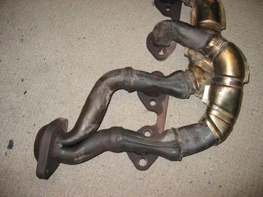
Passenger side exhaust manifold
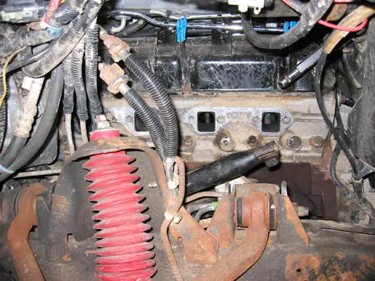
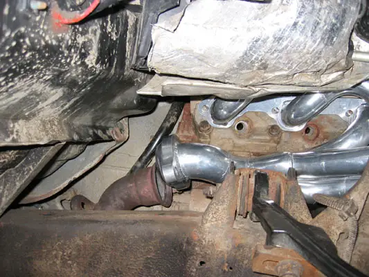
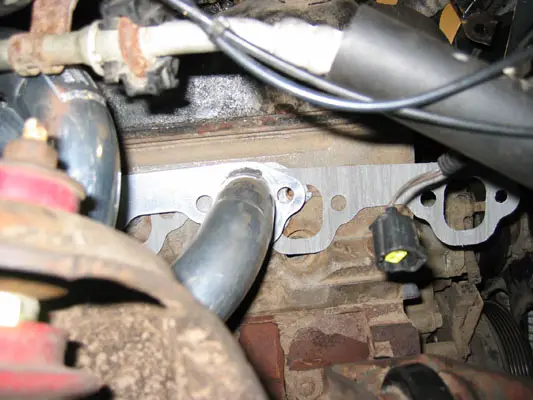
15) Remove the 8 manifold-to-head bolts, then remove the manifold. On the passenger side, the manifold is removed through the front of the engine compartment, above the A/C line and below the airbox's normal location.
Passenger side manifold removal
Manifold removed
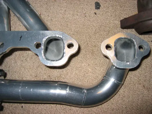
16) Comparison shots! Unlike the driver's side, the passenger header is one peice, and the tubes are almost equal in length.
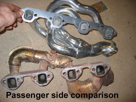
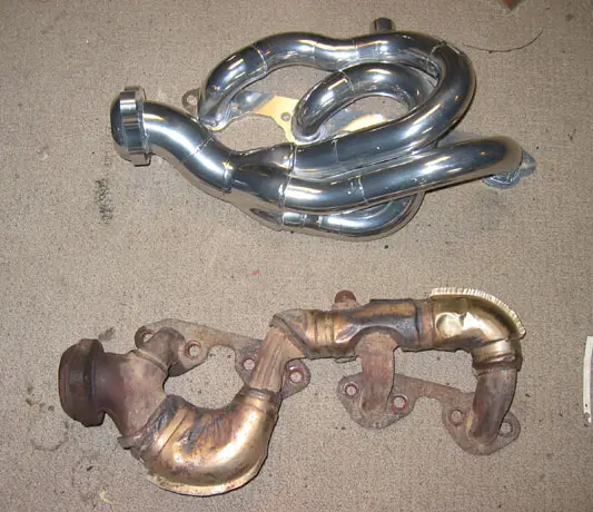
Passenger comparison, including port size.
17) Since the header's tubes straddle the engine mount nuts, the engine must be lifted 1" to allow the header to clear. The engine mount nuts are 18mm, and heavily torqued down. I used PB-Blaster, and a deep-well socket. I put a 2ft breaker bar (steel pipe) over the end of my Craftsman ratchet to gain enough leverage to break the nuts free. Notes:
a.The driver's side mount does not need to be touched.
b. Section525 did not have to complete this step because of his body lift raising the heaterbox 3" out of the way.
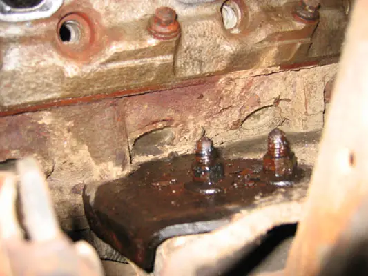
Passenger side engine mount nuts soaked in PB-Blaster
Do not remove the nuts, but merely bring them to the top of the motor mount studs. Through trial and error, I found the exact height of the nuts to be crucial. Don't go past the studs, or getting a wrench in to re-tighten them is impossible.
Nuts raised to their optimal height
18) Place a solid 2x4 block between the oil pan and a floorjack. Carefully jack up the motor untill the mount plate is touching the raise motor mount nuts.
Jacking up motor.
Engine raised.
19) Insert the header using the reverse procedure of the manifold's removal. This is where the header install gets tricky, and the part I had the most difficulty with. The header will clear the accessory bracket, forward upper control arm camber nut, shock tower and heaterbox. However, it must be finnessed into place, and then tipped back end down, forward end up to clear the motor mount nuts. If the exhaust downpipe is too far forward or inflexible, it will prevent this tilt. I coult not get the header to fit. While trading digital photos and talking on the phone with Robert Pasquale, Torque Monster's owner and the header's designer, we established that my downpipe was in the way. I then de-coupled the two downpipes (passenger and driver) from the rear cats and muffler, and wiggled the assembly aft.
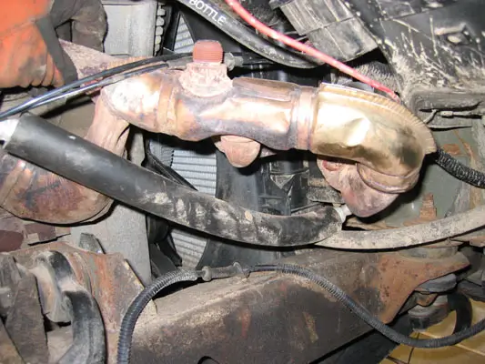
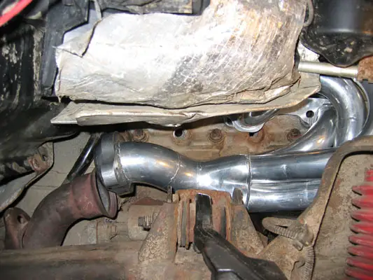
The downpipes are held on by two bolts per pipe. They will most likley be very rusty and seized, and need to be ground off. While this proved to be the solution on my truck, I am the only Torque Monster Header installer who has had to do this step... oh I love this truck.

Pass side downpipe disonnected
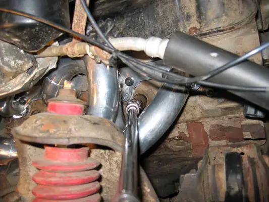
Due to my trial-and-error on inserting the header, I unfortunatley put some scratches in the ceramic coating, and wiped some rust-colored PB-Blaster on the headers. In the next photo, you can see how the tubes straddle the motor mount nuts.
Scratched tubes
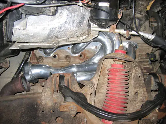
20) With the downpipe loose, the header has plenty of wiggle room. Once it is into position, and straddling the motor mount nuts, lower the motor back down onto its mount.
Header straddling nuts
Passenger header almost in
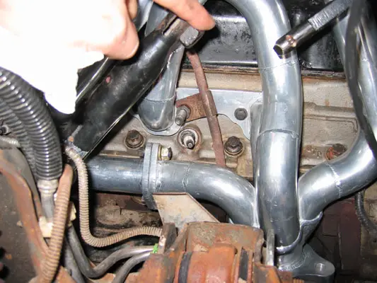
21) Re-tighten the engine mount nuts. The forward nut is easily accessible. The rear nut is a huge PITA, and can only be reached with an offset wrench. This tighetening took a very long time, and required holding the header up and out of the way, while taking miniscule turns on the wrench. These nuts are supposed to be torqued to 95ft-lbs; since I wasn't able to get a torque wrench on them, I just pulled until I couldn't pull anymore!
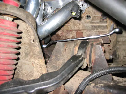
Tightening engine mount nuts
22) Insert the exhaust header gasket from the front. Bob supplies gaskets, bolts, and even the locktite needed with the headers.
Inserting gasket
23) Bolt up the header to the head. Normal procedure suggests that the outer two bolts be done first, but the extreme tube configuration means that the forward bolt on cylinder #4 needs to be inserted first.
Initiall bolting
24) Once the header bolts are properly torqued down to 30ft-lbs, re-install the sparkplugs. Here again, u-joints and extensions are a necessity.
Sparkplug installation
25) Now a fun project begins: Reshaping the EGR tube to accept the headers.
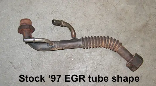
Original 1997 EGR shape
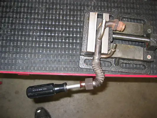
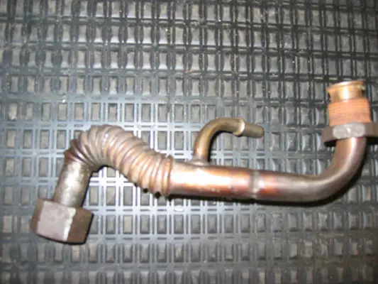
EGR final bench bend
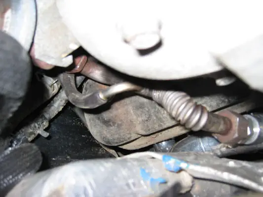
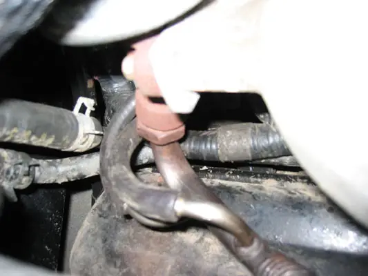
EGR tube re-installed
26) Torque Monster stainless steel spark plug heatsheilds, similar to the stock GT40P heatsheilds on cylinders 3-4 and 7-8, these are much thicker and go on all of the cylinders, except #3 - it won't fit due to the bend of the header tube. The old, thin Ford part did fit.
Heatsheilds on passenger side
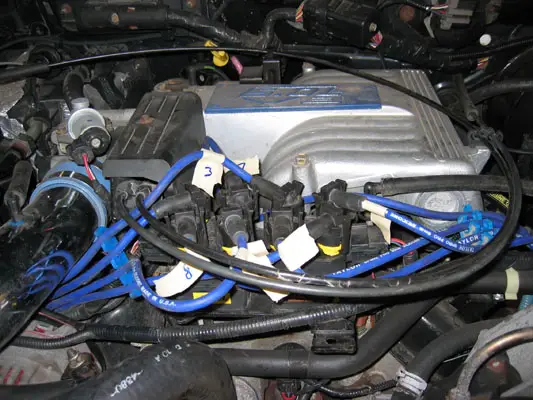
27) Ignition wire routing: I had purchased a set of 1998 Taylor Spira-Pro 8mm ignition wires from Summit Racing this past spring. I also purchased a set of TransDapt wire standoffs and wirelooms to aid in re-routing the ignition wires away from heat and moving parts. Everything fit really well, but took a few tires to get right, as the new wire layout is far from stock.
Taylor Spira-Pro wire with included heatsheild.
Cylinder 1&2 initial ignition wire routing
Cylinder 3&4 initial ignition wire routing
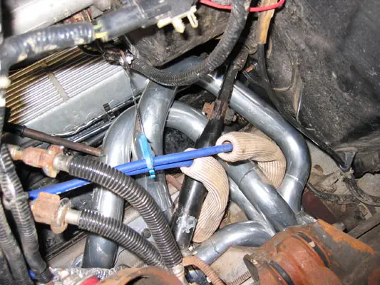
Passenger side wire routing, with wire heatshields, split-tubing for chafe protection, and wire standoffs.
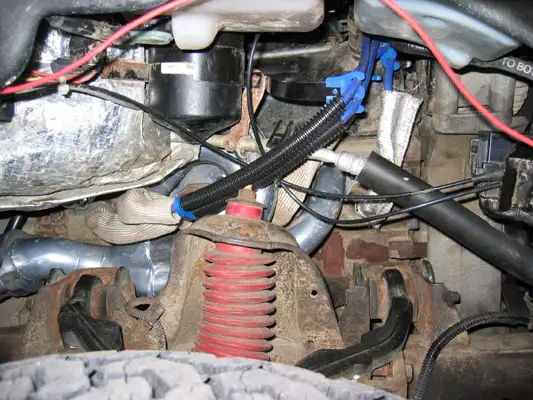
Driver's side ignition wire routing and wire standoffs
Always label your wires. I didn't and crossed two of them, yeilding a misfire. Don't rush, go slow, and always double check. I've had this ignition system apart many times, and made this stupid error.
Areas to monitor:
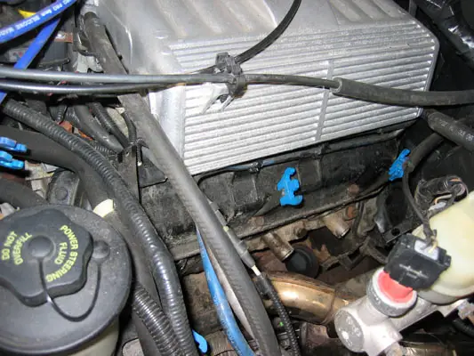
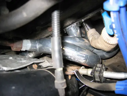
The following photo is of the clearance between the #4 primary tube and the A/C system orifice tube. It's less than 1/2", and I have been assured by Bob that this is more than enough clearance. Nevertheless, this is in the 'cold' line of the A/C system, and may hamper performance/soak in excess heat.
More to follow in the next few days
I spent the past weekend installing a new set of Tech Performance and Engineering's Torque Monster Headers on my Mountaineer. This post and thread will evolve over the next few days as a photo-documented "how-to" guide on installation of the headers, and a subsequent review of how they fit and how the performance of the Mountaineer has been increased. I will be editing this first post as the installation guide, the second post will the review. After that, let the comments begin!
Welded on TP&E logo, pass side header
Why Headers?
I had the stock manifolds out of the truck last June for my valve-job and head gasket repair (see: http://www.explorerforum.com/forums/showthread.php?t=108712 ) and could not believe how restrictive the design was. I had wanted headers at that point, but they were impossible to find. I am also always looking for bolt-on performance mods to increase the V8's power and/or gas mileage. While a supercharger may be the "ultimate" bolt on, bolting one on a 8 year old, 125k mile engine isn't the greatest recipe for reliability. A cam swap would mean discharging the A/C and substantial downtime. Headers on the otherhand, can be bolted on in a weekend, will increase power, and will not harm reliability. They are also a part that can be grown into, should I decide to cam or supercharge down the road (and would be a necessity anyway with said mods.)
Although the FMS headers were just re-released, they are very close in design to the stock manifolds, while the new Torque Monster headers are a much cooler design, with some neat technology behind them.
Tools Requied
Besides the usual compliment of wrenches, a few speciaity tools are needed. Don't make emergency parts runs like I did!
- A copious amount of 3/8" socket extensions and a good u-joint.
- 1/4" to 3/8" and 3/8" to 1/2" socket adapters.
- A good torque wrench.
- An 18mm offset wrench, for tightening the engine mount nuts.
Installation
(You'll have to excuse the salt, dirt, and surface rust. The weather has been really bad up here in Boston latley. Stay tuned for the big underbody painting thread come springtime.)
1) Jack up the truck, and support the lower a-arms or frame on jackstands. Remove wheels and fenderwell linings.
Passenger side fenderwell removed
Driver's side fenderwell removed
2) Remove the 13mm bolt that connects the steering shaft. This will allow the lower section of the shaft to be rotated out of the way during installation.
Steering shaft bolt
3) Remove all ignition wires and sparkplugs. Take the wires, and any mounting brackets completely off the engine. You'll be re-routing them once the headers are installed.
4) Remove manifold to downpipe bolts. There are two per manifold, and can be a pain to reach. U-joints and long extensions are a must.
Driver's side downpipe to manifold bolts. View looking up, camera placed next to front driveshaft.
5) Begin to remove the driver's side exhaust manifold to head bolts. Some are studs, some are nuts. The dipstick, bolted onto cylinder seven's aft stud, just pulls straight out from its hole in the block.
Dipstick assembly
6) Remove the driver's side exhaust manifold. With the steering shaft pointing vertical, it will wiggle out underneith the brake booster.
Removing the driver's side exhaust manifold, side view
Top View
7) With the manifold removed - compare it to the new header. My jaw dropped.
Collector Compasion, stock stamped vs. TM Modified Merge
Stock header
Torque Monster Ports
Driver's side manifold removed
8) Install driver's side header. The header comes in two parts, allowing easier installation around the steering shaft and fuel lines.
a. sperate the #5 cylinde tube from the header.
b. Insert the main header piece at the rear of the motor.
c. Drop in the #5 cylinder connector.
d. put one bolt in each header peice, then bolt the two together. It is important to loosely bolt the headers to the head before bolting the flange together.
Completed driver's side header
Driver's side Torque Monster Header top view
9) Re-attach dipstick. It will just press into fit, and then can be bolted down with the other 8 header bolts. Normally, a threaded stud will hold the header to the block, and the dipstick will be bolted speratly to the stud. However, the header tube is so close to the stud, the larger nut will not fit on. My dipstick is temporarily bolted below the stud's main nut, untill a smaller nut can be obtained.
Dipstick re-installed
Dipstick top view
10) Torque down all 8 header to head bolts, and the two flange connection bolts. Do NOT connect the header to the downpipe at this point, flexibility is needed when the motor is subsequently lifted from its passenger side mount.
11) Begin to disassemble the passenger side for header installation. Disconnect the MAF, IAT, and crankcase breather from the air intake tube, then remove the intake tube. Remove the air filter and MAF. Lastly, unbolt the bracket that supports the MAF/airbox and the foglight realy. Put it aside, there is no need to remove the foglight relay.
MAF support bracket. I have re-located the climate control vacuum reserve sphere to the upper fender, rather than have it be attached to the fenderwell lining. This 'mini-mod' was done last year during my aux trans filter install.
12) Remove the lower EGR tube-to-manifold connection. I used an adjustible wrench, as none of my combination wrenchs were large enough. Your miliage may vary.
Lower EGR tube-to-manifold nut
13) Remove the EGR vacuum hoses and the upper EGR nut.
Upper EGR nut
14) Remove the passenger side manifold-to-downpipe connection. I have liberally applied PB-Blaster to the bolt threads.
Passenger side exhaust manifold
15) Remove the 8 manifold-to-head bolts, then remove the manifold. On the passenger side, the manifold is removed through the front of the engine compartment, above the A/C line and below the airbox's normal location.
Passenger side manifold removal
Manifold removed
16) Comparison shots! Unlike the driver's side, the passenger header is one peice, and the tubes are almost equal in length.
Passenger comparison, including port size.
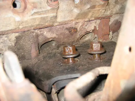
17) Since the header's tubes straddle the engine mount nuts, the engine must be lifted 1" to allow the header to clear. The engine mount nuts are 18mm, and heavily torqued down. I used PB-Blaster, and a deep-well socket. I put a 2ft breaker bar (steel pipe) over the end of my Craftsman ratchet to gain enough leverage to break the nuts free. Notes:
a.The driver's side mount does not need to be touched.
b. Section525 did not have to complete this step because of his body lift raising the heaterbox 3" out of the way.
Passenger side engine mount nuts soaked in PB-Blaster
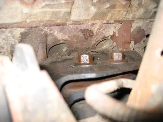
Do not remove the nuts, but merely bring them to the top of the motor mount studs. Through trial and error, I found the exact height of the nuts to be crucial. Don't go past the studs, or getting a wrench in to re-tighten them is impossible.
Nuts raised to their optimal height
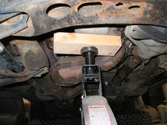
18) Place a solid 2x4 block between the oil pan and a floorjack. Carefully jack up the motor untill the mount plate is touching the raise motor mount nuts.
Jacking up motor.
Engine raised.
19) Insert the header using the reverse procedure of the manifold's removal. This is where the header install gets tricky, and the part I had the most difficulty with. The header will clear the accessory bracket, forward upper control arm camber nut, shock tower and heaterbox. However, it must be finnessed into place, and then tipped back end down, forward end up to clear the motor mount nuts. If the exhaust downpipe is too far forward or inflexible, it will prevent this tilt. I coult not get the header to fit. While trading digital photos and talking on the phone with Robert Pasquale, Torque Monster's owner and the header's designer, we established that my downpipe was in the way. I then de-coupled the two downpipes (passenger and driver) from the rear cats and muffler, and wiggled the assembly aft.
The downpipes are held on by two bolts per pipe. They will most likley be very rusty and seized, and need to be ground off. While this proved to be the solution on my truck, I am the only Torque Monster Header installer who has had to do this step... oh I love this truck.
Pass side downpipe disonnected
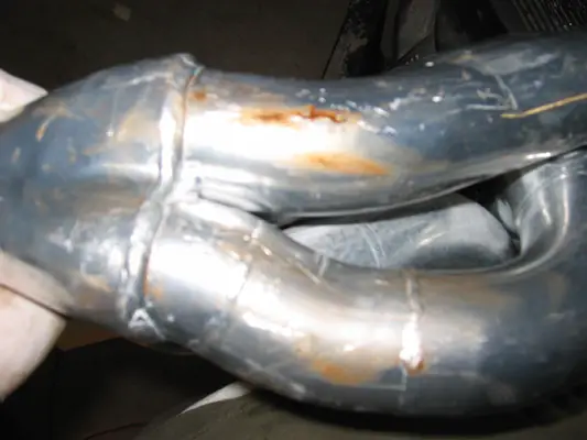
Due to my trial-and-error on inserting the header, I unfortunatley put some scratches in the ceramic coating, and wiped some rust-colored PB-Blaster on the headers. In the next photo, you can see how the tubes straddle the motor mount nuts.
Scratched tubes
20) With the downpipe loose, the header has plenty of wiggle room. Once it is into position, and straddling the motor mount nuts, lower the motor back down onto its mount.
Header straddling nuts
Passenger header almost in
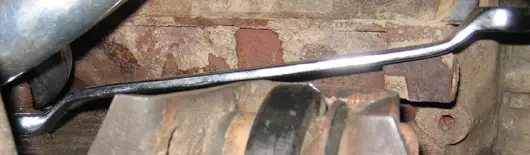
21) Re-tighten the engine mount nuts. The forward nut is easily accessible. The rear nut is a huge PITA, and can only be reached with an offset wrench. This tighetening took a very long time, and required holding the header up and out of the way, while taking miniscule turns on the wrench. These nuts are supposed to be torqued to 95ft-lbs; since I wasn't able to get a torque wrench on them, I just pulled until I couldn't pull anymore!
Tightening engine mount nuts
22) Insert the exhaust header gasket from the front. Bob supplies gaskets, bolts, and even the locktite needed with the headers.
Inserting gasket
23) Bolt up the header to the head. Normal procedure suggests that the outer two bolts be done first, but the extreme tube configuration means that the forward bolt on cylinder #4 needs to be inserted first.
Initiall bolting
24) Once the header bolts are properly torqued down to 30ft-lbs, re-install the sparkplugs. Here again, u-joints and extensions are a necessity.
Sparkplug installation
25) Now a fun project begins: Reshaping the EGR tube to accept the headers.
Original 1997 EGR shape
EGR final bench bend
EGR tube re-installed
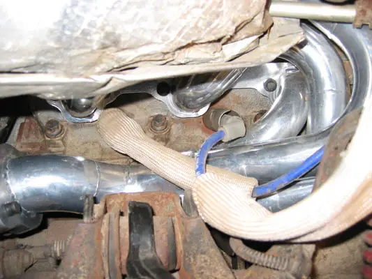
26) Torque Monster stainless steel spark plug heatsheilds, similar to the stock GT40P heatsheilds on cylinders 3-4 and 7-8, these are much thicker and go on all of the cylinders, except #3 - it won't fit due to the bend of the header tube. The old, thin Ford part did fit.
Heatsheilds on passenger side
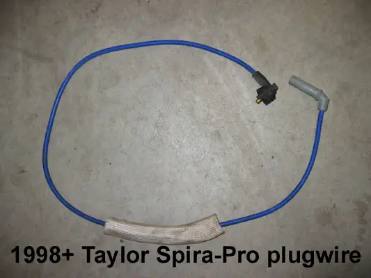
27) Ignition wire routing: I had purchased a set of 1998 Taylor Spira-Pro 8mm ignition wires from Summit Racing this past spring. I also purchased a set of TransDapt wire standoffs and wirelooms to aid in re-routing the ignition wires away from heat and moving parts. Everything fit really well, but took a few tires to get right, as the new wire layout is far from stock.
Taylor Spira-Pro wire with included heatsheild.
Cylinder 1&2 initial ignition wire routing
Cylinder 3&4 initial ignition wire routing
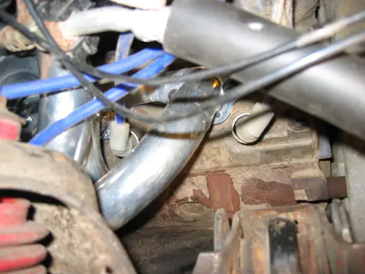
Passenger side wire routing, with wire heatshields, split-tubing for chafe protection, and wire standoffs.
Driver's side ignition wire routing and wire standoffs
Always label your wires. I didn't and crossed two of them, yeilding a misfire. Don't rush, go slow, and always double check. I've had this ignition system apart many times, and made this stupid error.
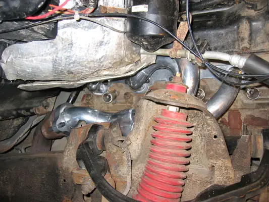
Areas to monitor:
The following photo is of the clearance between the #4 primary tube and the A/C system orifice tube. It's less than 1/2", and I have been assured by Bob that this is more than enough clearance. Nevertheless, this is in the 'cold' line of the A/C system, and may hamper performance/soak in excess heat.
More to follow in the next few days