Ford Explorer Community - Maintenance - Modifications - Performance Upgrades - Problem Solving - Off-Road - Street
Register Today
JavaScript is disabled. For a better experience, please enable JavaScript in your browser before proceeding.
You are using an out of date browser. It may not display this or other websites correctly.
You should upgrade or use an
alternative browser .
BrooklynBay Media item
May 27, 2009
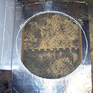
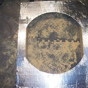
a
all
around
bead
is
of
opening
silicone
the
Comments: 0
Category: General Photo Album
BrooklynBay Media item
May 27, 2009
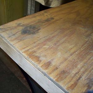
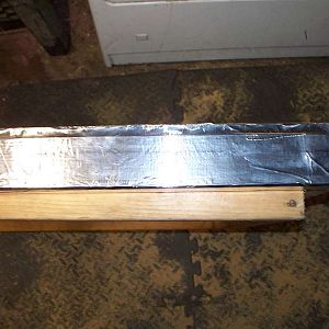
connected
getting
is
the
top
wood
Comments: 0
Category: General Photo Album
BrooklynBay Media item
May 27, 2009
connected
is
the
top
wood
Comments: 0
Category: General Photo Album
BrooklynBay Media item
May 27, 2009
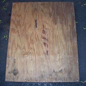
cut
is
off.
the
top
Comments: 0
Category: General Photo Album
BrooklynBay Media item
May 27, 2009
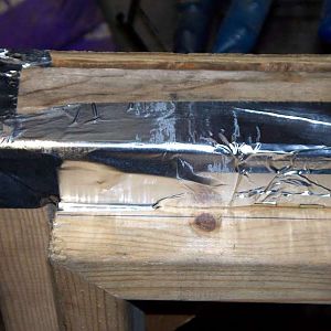
aluminum
covered
foil
is
tape
the
top
with
Comments: 0
Category: General Photo Album
BrooklynBay Media item
May 27, 2009
is
out
smoothed
tape
the
Comments: 0
Category: General Photo Album
BrooklynBay Media item
May 27, 2009
applied
being
is
tape
the
Comments: 0
Category: General Photo Album
BrooklynBay Media item
May 27, 2009
a
as
hemisphere
is
template
the
used
Comments: 0
Category: General Photo Album
BrooklynBay Media item
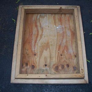
May 27, 2009
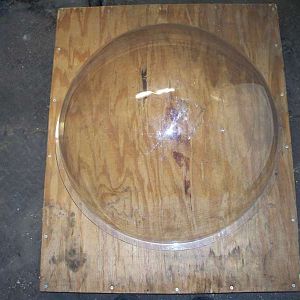
back
of
skylight
the
top
with
wood
Comments: 0
Category: General Photo Album
BrooklynBay Media item
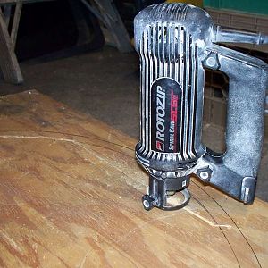
May 27, 2009
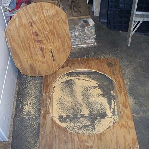
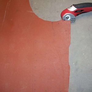
a
cutting
is
out
rotozip
the
top
Comments: 0
Category: General Photo Album
BrooklynBay Media item
May 6, 2009
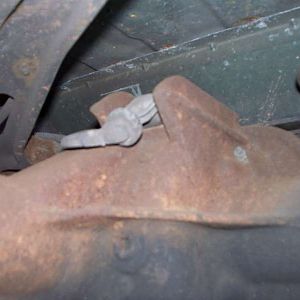
area
brake
is
located
parking
switch
the
where
Comments: 0
Category: General Photo Album
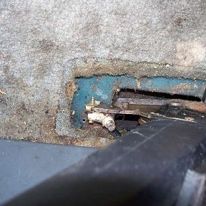
BrooklynBay Media item
May 6, 2009
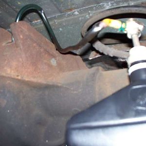
area
brake
dirt
gets
in
parking
switch
the
this
Comments: 0
Category: General Photo Album
BrooklynBay Media item
May 6, 2009
removing
screw
the
upper
Comments: 0
Category: General Photo Album
BrooklynBay Media item
May 6, 2009
lower
removing
screw
the
Comments: 0
Category: General Photo Album
BrooklynBay Media item
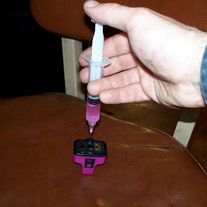
April 28, 2009
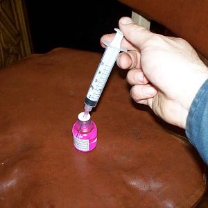
cartridge
injecting
ink
into
the
Comments: 0
Category: General Photo Album
BrooklynBay Media item
April 28, 2009
bottle
drawing
ink
of
out
the
Comments: 0
Category: General Photo Album
BrooklynBay Media item
April 26, 2009
and
bottom
in
is
next
one
pin
the
top
Comments: 0
Category: General Photo Album
BrooklynBay Media item
April 26, 2009
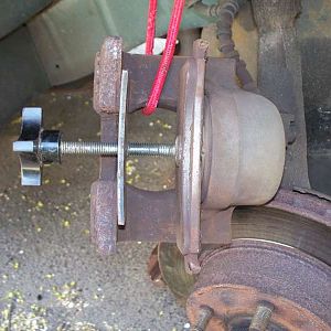
back
being
into
is
piston
place
pushed
the
Comments: 0
Category: General Photo Album
BrooklynBay Media item
April 26, 2009
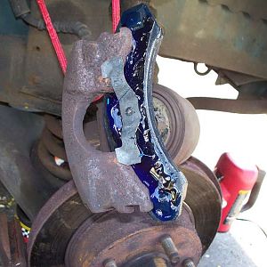
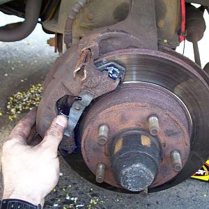
anti
have
new
pads
paste
squeal
the
Comments: 0
Category: General Photo Album
BrooklynBay Media item
April 26, 2009
are
back
caliper
going
into
pins
place
the
Comments: 0
Category: General Photo Album
BrooklynBay Media item
April 26, 2009
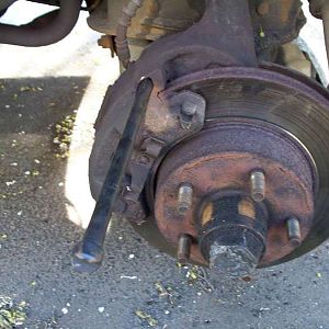
bolt
caliper
is
out
pin
pushing
the
tool
Comments: 0
Category: General Photo Album
BrooklynBay Media item
April 26, 2009
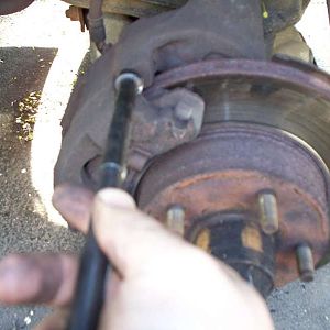
a
caliper
groove
handle
has
on
pin
the
tool
Comments: 0
Category: General Photo Album
BrooklynBay Media item
April 26, 2009
caliper
coming
is
out
the
Comments: 0
Category: General Photo Album
BrooklynBay Media item
April 26, 2009
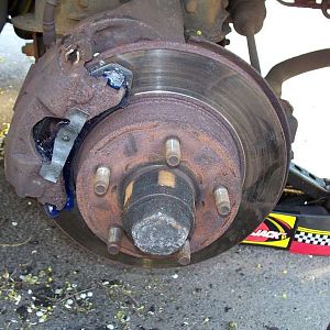
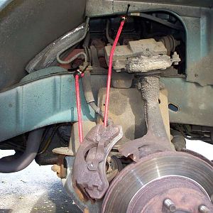
a
bungee
caliper
cord
holding
is
stretch
the
Comments: 0
Category: General Photo Album
BrooklynBay Media item
April 8, 2009
abs
differential
of
on
rear
sensor
the
top
Comments: 0
Category: General Photo Album
BrooklynBay Media item
April 8, 2009
adding
differential
fluid
hole
into
sensor
the
Comments: 0
Category: General Photo Album
BrooklynBay Media item
April 8, 2009
a
of
reluctor
ring
the
view
Comments: 0
Category: General Photo Album
BrooklynBay Media item
April 8, 2009
a
bolt
box
is
removing
the
wrench
Comments: 0
Category: General Photo Album
BrooklynBay Media item
March 31, 2009
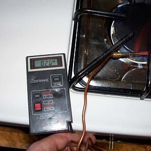
a
dmm
testing
the
the rmocouple
with
Comments: 0
Category: General Photo Album
BrooklynBay Media item
March 24, 2009
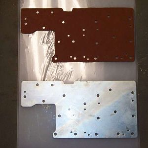
air
finished
gasket
plate
test
the
with
Comments: 0
Category: General Photo Album
BrooklynBay Media item
March 24, 2009
a
being
cut
gasket
larger
of
the
view
Comments: 0
Category: General Photo Album
BrooklynBay Media item
December 28, 2008
installed
is
switch
the
Comments: 0
Category: General Photo Album
BrooklynBay Media item
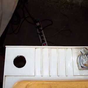
December 28, 2008
1
1/2"
hole
in
is
sink
the
Comments: 0
Category: General Photo Album
BrooklynBay Media item
December 28, 2008
a
groove
lock
nut
retaining
the
with
Comments: 0
Category: General Photo Album
BrooklynBay Media item
December 28, 2008
pressure
switch
the
Comments: 0
Category: General Photo Album
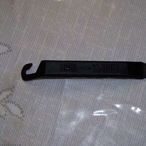
BrooklynBay Media item
September 22, 2008
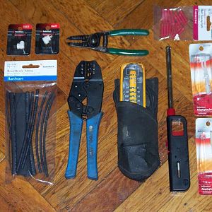
connector
for
parts
power
repairing
the
tools
with
Comments: 0
Category: General Photo Album
BrooklynBay Media item
September 22, 2008
connections
crimping
the
Comments: 0
Category: General Photo Album
BrooklynBay Media item
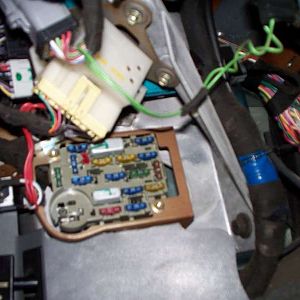
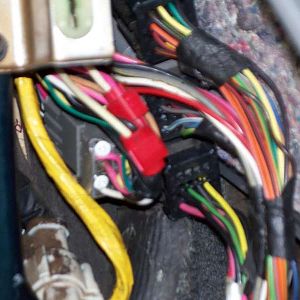
August 28, 2008
door
fuse
green
is
left
lock
on
power
stripe
the
with
Comments: 0
Category: General Photo Album
BrooklynBay Media item
August 28, 2008
bulk
door
head
lock
repaired
the
wiring
with
Comments: 0
Category: General Photo Album
BrooklynBay Media item
August 24, 2008
inner
installation
of
the
tool
top
tube
view
Comments: 0
Category: General Photo Album