-
Ford Explorer Community - Maintenance - Modifications - Performance Upgrades - Problem Solving - Off-Road - Street
Explorer Forum Covers the Explorer ST, Explorer Sport, Explorer Sport Trac, Lincoln Aviator,
Mercury Mountaineer, Mazda Navajo, Ford Ranger, Mazda Pickups, and the Ford Aerostar
Register Today It's free!
the
-
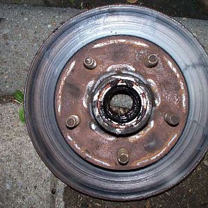
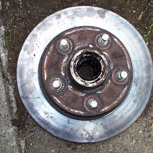
The front of the rotor.
- BrooklynBay
- Media item
- front of rotor the
- Comments: 0
- Category: General Photo Album
-
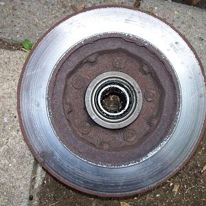
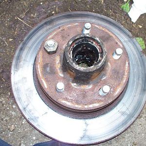
The back of the rotor.
- BrooklynBay
- Media item
- back of rotor the
- Comments: 0
- Category: General Photo Album
-
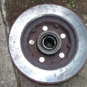
Rear view of the rotor with new studs.
- BrooklynBay
- Media item
- new of rear rotor studs the view with
- Comments: 0
- Category: General Photo Album
-
Hanson die # 9445 going over the threads.
- BrooklynBay
- Media item
- 9445 die going hanson over the threads
- Comments: 0
- Category: General Photo Album
-
Front view of the rotor with new studs.
- BrooklynBay
- Media item
- front new of rotor studs the view with
- Comments: 0
- Category: General Photo Album
-
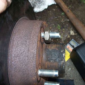
A wheel nut (lug nut) pulls the stud into position.
- BrooklynBay
- Media item
- (lug a into nut nut) position pulls stud the wheel
- Comments: 0
- Category: General Photo Album
-
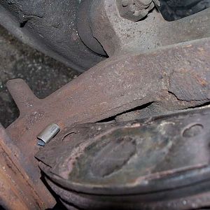
Close up view of the anti-rattle clip.
- BrooklynBay
- Media item
- anti-rattle clip close of the up view
- Comments: 0
- Category: General Photo Album
-
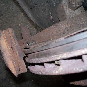
Anti-rattle clip on the inner brake pad.
- BrooklynBay
- Media item
- anti-rattle brake clip inner on pad the
- Comments: 0
- Category: General Photo Album
-
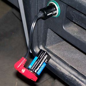
The memory saver is plugged in.
- BrooklynBay
- Media item
- in is memory plugged saver the
- Comments: 0
- Category: General Photo Album
-
Remove the hood bulb to avoid draining the 9 volt battery.
- BrooklynBay
- Media item
- 9 avoid battery bulb draining hood remove the to volt
- Comments: 0
- Category: General Photo Album
-

Memory saver for the computer & clock.
- BrooklynBay
- Media item
- & clock computer for memory saver the
- Comments: 0
- Category: General Photo Album
-
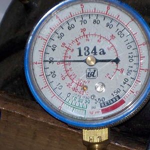
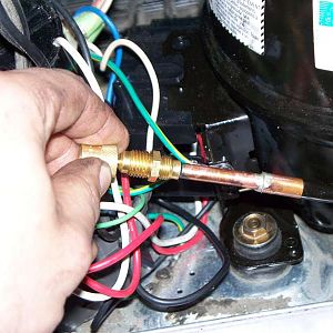
The proper amount of pressure for the system to work.
- BrooklynBay
- Media item
- amount for of pressure proper system the to work
- Comments: 0
- Category: General Photo Album
-
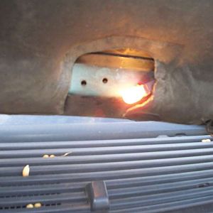
The mounting bolts are tightened.
- BrooklynBay
- Media item
- are bolts mounting the tightened
- Comments: 0
- Category: General Photo Album
-
The core is reinstalled.
- BrooklynBay
- Media item
- core is reinstalled the
- Comments: 0
- Category: General Photo Album
-
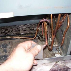
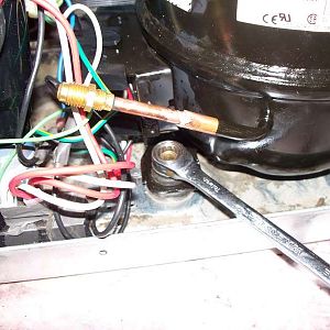
The copper lines require preparation before installation.
- BrooklynBay
- Media item
- before copper installation lines preparation require the
- Comments: 0
- Category: General Photo Album
-
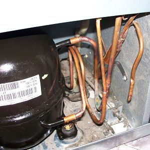
The copper lines are inserted into the compressor.
- BrooklynBay
- Media item
- are compressor copper inserted into lines the
- Comments: 0
- Category: General Photo Album
-

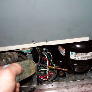
The compressor needs preparation before installation.
- BrooklynBay
- Media item
- before compressor installation needs preparation the
- Comments: 0
- Category: General Photo Album
-

Refilling the squeeze bottle with oil.
- BrooklynBay
- Media item
- bottle oil refilling squeeze the with
- Comments: 0
- Category: General Photo Album
-
Oil is added to the compressor.
- BrooklynBay
- Media item
- added compressor is oil the to
- Comments: 0
- Category: General Photo Album
-
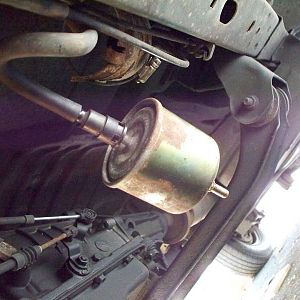
The old fuel filter is being disconnected.
- BrooklynBay
- Media item
- being disconnected filter fuel is old the
- Comments: 0
- Category: General Photo Album
-
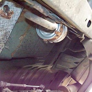
The new fuel filter is installed!
- BrooklynBay
- Media item
- filter fuel installed is new the
- Comments: 0
- Category: General Photo Album
-
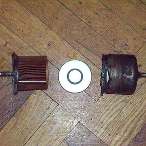
The inside of the old fuel filter.
- BrooklynBay
- Media item
- filter fuel inside of old the
- Comments: 0
- Category: General Photo Album
-
The overload relay with the start capacitor.
- BrooklynBay
- Media item
- capacitor overload relay start the with
- Comments: 0
- Category: General Photo Album
-
The old overload relay & mounting clip.
- BrooklynBay
- Media item
- & clip mounting old overload relay the
- Comments: 0
- Category: General Photo Album
-

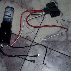
The new overload relay wired into the compressor.
- BrooklynBay
- Media item
- compressor into new overload relay the wired
- Comments: 0
- Category: General Photo Album
-

The new overload relay.
- BrooklynBay
- Media item
- new overload relay the
- Comments: 0
- Category: General Photo Album
-

The location of the overload relay.
- BrooklynBay
- Media item
- location of overload relay the
- Comments: 0
- Category: General Photo Album
-

The inside of the old overload relay.
- BrooklynBay
- Media item
- inside of old overload relay the
- Comments: 0
- Category: General Photo Album
-

The back panel on the refrigerator.
- BrooklynBay
- Media item
- back on panel refrigerator the
- Comments: 0
- Category: General Photo Album
-

The 3 prongs on the compressor.
- BrooklynBay
- Media item
- 3 compressor on prongs the
- Comments: 0
- Category: General Photo Album
-
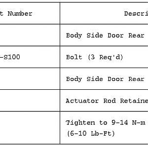
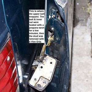
Description for the sliding door latch diagram.
This is the description for the Aerostar sliding door latch diagram. The break out view has numbers. This description explains those numbers.- BrooklynBay
- Media item
- description diagram door for latch sliding the
- Comments: 0
- Category: General Photo Album
-
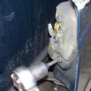
The old latch is being removed.
- BrooklynBay
- Media item
- being is latch old removed the
- Comments: 0
- Category: General Photo Album
-
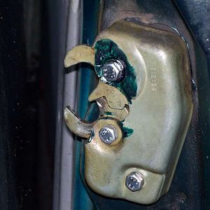
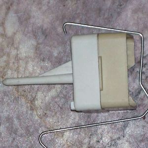
The new latch is installed!
- BrooklynBay
- Media item
- installed is latch new the
- Comments: 0
- Category: General Photo Album
-
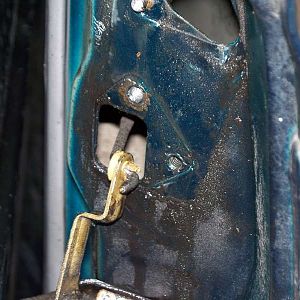
The lower linkage on the latch.
- BrooklynBay
- Media item
- latch linkage lower on the
- Comments: 0
- Category: General Photo Album
-
The latch is removed.
- BrooklynBay
- Media item
- is latch removed the
- Comments: 0
- Category: General Photo Album
-
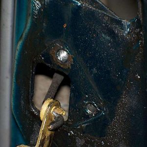
The 3 holes have 6 MM nuts in the door.
- BrooklynBay
- Media item
- 3 6 door have holes in mm nuts the
- Comments: 0
- Category: General Photo Album
-
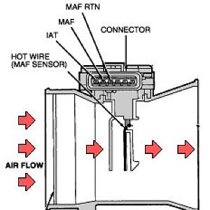
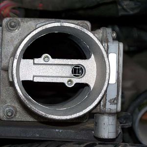
This is how the Mass Air Flow (MAF) works.
- BrooklynBay
- Media item
- air flow how is maf mass the this works
- Comments: 0
- Category: General Photo Album
-
Opposite side of the Mass Air Flow sensor (MAF).
- BrooklynBay
- Media item
- air flow maf mass of opposite sensor side the
- Comments: 0
- Category: General Photo Album
-
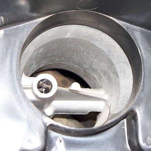
1995 Mass Air Flow (MAF) with the block off plate removed.
- BrooklynBay
- Media item
- air block flow maf mass off plate removed the with
- Comments: 0
- Category: General Photo Album
-
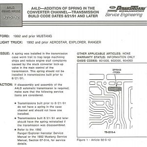
TSB 92-5-12 Case spring in the converter channel of an A4LD transmission.
A spring was installed in the transmission case worm trail to trap large machining chips, and reduce engine stall complaints caused by the stuck converter lock-up valve in the main control of the transmission. This spring should not be installed in transmissions built prior to 8/21/91.- BrooklynBay
- Media item
- 92-5-12 a4ld an case channel converter in of spring the transmission tsb
- Comments: 0
- Category: General Photo Album