1997 MM 5.0 TC & WP refresh & ignition coil-near-plug conversion-Temporarily on hold- | Page 16 | Ford Explorer Forums - Serious Explorations

  • Register Today It's free!

1997 MM 5.0 TC & WP refresh & ignition coil-near-plug conversion-Temporarily on hold-

Sexy! I have no knowledge on the crown Vic stuff ;) closest I get is 02-07 exploders… I crush them for their engines, seats, wheels, tires and cats lol lol


Join the Elite Explorers for $20 each year.
Elite Explorer members see no advertisements, no banner ads, no double underlined links,.
Add an avatar, upload photo attachments, and more!
.


@410Fortune Where you able to see the pic that I pm'd you?
I has confirmed that pin #45 is where the CHT goes.


Yes! I did just now. However you are installing a 5.0 into an explorer I would stick with one sender for the computer and one for the dash, this is what your instrument cluster is expecting to see. Unless you are using the crown Vic cluster… I’m worried the signal may not be the same? Not sure


I'm wired like the 97MM on those specific 2 things. I'm using the MM harness. It has the traditional rd/wh temp sending unit wire with this gauge sender on the 5.0 intake. I'm plugged onto this on the left front of the intake for the gauge.
1997mm temp sending unit.jpg

The ECT sensor wire will be hooked to this.
1997mm ECT sensor.JPG

I got confused when the wire change color. 97MM #38 lg/rd gets pinned in on the 99CV pin #45 that on the Crown Vic is a or/rd wire.
Yesterday I looked at the 99CV harness and confirmed that the or/rd wire connector was plugged into the ECT sensor.
Jamie, I was showing you the odd way on the 1999 Crown Vic that I discovered that the gauge feed was odd that it came from the PCM.


This evening I finished everything transmission as far as the wiring goes. The last thing that I did was repin the C-180 transmission connector.
The 97 MM had 3 power wires and the 99 CV way has one. They are all red and numbered 361. does it matter which one that you use?
Then can I simply put heat shrink on them, fold them back against the harness and tape them with the rest of the pigtail?
1997mm c180 connector.jpg

I had to drill out the plastic in hole #8.


They are all the same power wire
Upstream. Yes just clip them and wrap them up!
This is another example of Cost engineering, imagine how much ford saves by eliminating 18’ of 12ga copper wire on every truck

Well done again!


Insulated and ready to wrap in the harness. I've checked the pin wiring again.
1997mm c180 rtw.jpg


@410Fortune I upgraded to the 2 wire camshaft position sensor and want to double check the wiring change. I t was 3 wires and one of them was a black stripe. Another, the blue/orange stripe I hooked up the same as the 3 wire bl/or, however I cut the black/wh and spliced into a gray/rd signal return. Are or do all gray/rd signal return go to the same place? I wanted to make sure before anymore tape wrap goes on that I have this correct. I haven't noticed a designated return for Cam pos sen in the charts.
I brought the harness to work to make sure that I get the coil wires positioned properly.
1997mm powertrain harness 3-07-24.jpg


Yes ssr or sensor signal return is a single wire goes to many sensors
The impedance of each sensor has a range sent to the pcm, so a single wire allows the pcm to monitor several sensors at a time


Today, I worked on the harness for the most part. I did take a few minutes to make a template and draw on the 3/16" scrap (drop)
leftover from the bracket cutting. From time to time, I need to make little aluminum pieces. Friday morning I will rough cut this part out.
1997mm egr block off plate pattern.jpg

1997mm egr block off plate pattern marked.jpg

On the harness, I got the rh passenger USA side of the fuel injector/coil wires roughed in. Then I ran out of my smaller sizes of heat shrink
tubing that I was using for the second layer of shrink. Walmart has a good package available in sporting goods in the marine section. The automotive section has some but it didn't look very good. The little case full was $4.98+tax. $5.20.
walmart marine heat shrink.jpg

(These empty containers would be good for garden seeds or make a pocket size tackle box...)
I'll keep going tomorrow. I still need to splice in the new injector connectors and crimp on the coil connectors too. I have been staying up equivalent to nearly midnight working on this harness. I'm still looking for the misplaced oxygen and acetylene gauges. They shouldn't be
too deep under stuff at the shop but it is always seems like an archeological dig there.
I have someone that says he will buy the 1997 SOHC driver, beater when I get the Mountaineer going again. I'm trying to stay on it and get
it going ASAP.


Earlier I was looking for some hood struts for the '97 MM. I wonder if these are any good and if they will last more that a year.
Amazon hood lift supports. I rough cut the EGR bockoff plate really quick with the sawsall. The little jigsaw would have made a hobby out of it.
1997mm egr block off plate rough cut.jpg

After a little more trimming, filed then belt sanded.
1997mm egr block off plate belt sanded.jpg

Holes drilled then done.
1997mm egr block off plate done.jpg

Ron Francis Ford EGR block off plate


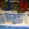
At work where the Mountaineer is, I've been rotating on 5 vehicles so the '97 MM is just getting a little of that time. The wiring harness is near complete with the exception of the coil connectors being installed. The rh valve cover had to come off to install the 1/2" pipe thread bung that
will be where a long skinny transmission funnel will go in to put in the motor oil. Also a 1/2"pipe x 3/8" barb fitting will screw in to this bung to have a place to hook up the rubber line that used to attach to the old oil fill tube that had to be deleted for coil clearance.
My welding didn't turn out quite like I wanted it to and I'm having to dress it up a bit with a round file. (Not done)
1997mm rh valve cover oil fill bung.jpg

Saturday March 9th I accumulated some more parts for my 54F100/99Ranger project and attached to the fox body style fuel rail was this
oil filled fuel gauge. It's a Marshall 1.5. It installs in place of the Schrader bleed valve. I have two brass 90's on the way to see if there is a
way to position it such that you see it peeking out from under the upper plenum.
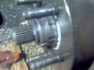
I was able to remove the fuel rails and injectors by the hardest. The old O rings were so dried out that they tore to get them removed.
Also the injector bores had a ring of oxidation at the top of each hole. Usually the rail and injectors slide right out. New injectors and the
old rail/s are ready to go back on. With the valve cover back on and the coil bracket plates on, the powertrain harness can go back on.
1997mm fuel pressure gauge.jpg

That is the oil that you see shifting and not a broken gauge.
More later.


The rh (US) valve cover oil fill bung has been installed and the valve cover is on for the last time. The barbed fitting attaches to a hose on the throttle body. You remove the fitting to put oil in.
1997mm oil fill bung 03.jpg

1997mm oil fill bung 04.jpg


I'm looking for a spot to add an intake manifold dry temperature sensor. What is this threaded hole for where the Allen head pipe plug is installed? Does it open into a water port, the front intake runner or a solid aluminum spot in the intake?
1994 mustang lower plenum left front side plugged hole.jpg

A picture of the same spot that hasn't been drilled and tapped.
1994 mustang lower intake solid spot.jpg


You sure you want the temp sensor in the lower intake and not the upper?


I'm not sure. Upper would probably be better. I want to add a gauge to measure the intake temp without EGR and On brother's MM install a gauge too to compare with EGR. I'm really not sure what kind of gauge and sending unit for this either. I'm more or less wanting to read the dry aluminum tempurature.


Interesting! There is already an iat sensor taking a similar temp
An infared thermo can give you a surface temp in various places.
I find once you have a gauge and get to know the operating temps and how things are supposed to look, basically that gauge is not needed anymore (like a boost gauge, boost is cool to see but the egt gauge is the one that really matters)!


I'm looking for a spot to add an intake manifold dry temperature sensor. What is this threaded hole for where the Allen head pipe plug is installed? Does it open into a water port, the front intake runner or a solid aluminum spot in the intake?
View attachment 450946
A picture of the same spot that hasn't been drilled and tapped.
View attachment 450947

That is the IAT location for all SBF EFI intakes before the mid 90's V8's. The later models have it in the inlet pipe leading to the throttle body, which is a little cooler but mainly less damaging to the sensor. The old IAT sensors are reliable, but they do degrade over 15-20 years. The type in the Explorers rubber inlet pipe can last forever.


Here is a head surface, of a sort, temperature sensor that sits between the spark plug and head. I've not seen one of these.
CHT on Amazon
amazon CHT kit.JPG


Join the Elite Explorers for $20 each year.
Elite Explorer members see no advertisements, no banner ads, no double underlined links,.
Add an avatar, upload photo attachments, and more!
.


I'm not sure how much money that I'm starting to get in the ss braided fuel lines. I had originally bought 2 sets of the Ford QD to -AN adapters but it turns out that the pair of lines at the frame rail had male Ford ends, so I had to get Ford female QD to male -AN adapters. The -6 one from Canada got here faster than the -8 one from Columbus GA/Phoenix City AL. Also a 45 -8 AN had to be ordered for the upper fuel rail.
The straight hit the firewall. The -6 AN line is fitted and finished and there are still the two fittings for the -8 AN to go. Then the lines come back off to install the power train harness. -6 line in picture below.
1997mm ss braided fuel line 00.jpg

-6 AN return line finished. -8 AN not.
1997mm ss braided fuel line 01.jpg

View from the top.
1997mm ss braided fuel line 03.jpg

I'm still waiting on the fittings and the special AN wrenches. I will pressure test the fuel system before installing the harness and upper
plenum. The pump is hot wired at the inertia switch from removing the old fuel. The pump can be run without the missing harness.


Back
Top