ShadowRaven
Well-Known Member
- Joined
- October 7, 2008
- Messages
- 411
- Reaction score
- 2
- City, State
- Richmond Hill, GA
- Year, Model & Trim Level
- '02 Sport
Hey, guys, your friendly neighborhood ShadowRaven here doing my first write-up on this forum, so here's hoping it will all go smoothly, lol. I'll try to make this as detailed as possible, as well as make it as easy to follow as possible. This write-up has the purpose to turn your Explorer from this

To this

This write-up will be composed of the following sections:
1. Materials and Prepwork
2. Fascia Removal
3. Front and Rear Bumper Removal
4. Dropping the Radiator
5. Extending the Steering Linkage
6. The Bodylift Itself
7. Reinstallation
7a. Front and Rear Bumper Installation
7b. Fascia Installation
8. Cleanup and Final Results
Section 1: Materials and Prepwork
The kit (which can be ordered online) includes all that is shown below:
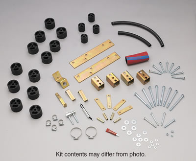
Inspect the kit using the included parts list and become intimately familiar with all the parts to help expedite the installation process and prevent any unnecessary stress that may arise if you don’t know what part is needed for what.
Materials:
- PA 883 3” Bodylift kit
- 4x4” wood blocks, minimum of 12” in length to act as temporary jack ‘extensions’
- Jacks (I used two 4-ton bottle jacks)
- A pair of Jackstands
- 1/4, 3/8, 1/2 inch socket sets with available breaker bar
- Sawzall (or something similar, I used a 4” Angle Grinder)
- Box Cutter (or similar razor)
- Propane Torch (this was extremely beneficial to have, but not required)
- Flint Striker (to light the propane torch)
- Vice Grips
- Sheet Metal Cutters (or something similar)
- Threadlocker (included in kit, but I purchased an extra tube)
- Drill with drill bits up to 1/2” (preferably 18V or corded)
- PB Blaster (not required, but helps to loosen the stock bolts)
- Mechanics gloves (not required, but I’m glad I bought some)
- Safety Glasses/Goggles
- Tape Measurer
- Sharpie
- Hammer
- Sledgehammer (or similar beating device)
- Ample Time (in the area of 2-5 days)
- LOTS OF PATIENCE
Optional Materials:
- Air Impact Wrench (for tightening body to frame bolts)
- An extra car to get extra materials if needed from your local hardware store
- Energy drinks or beer
- Cigarettes (if you smoke obviously)
Prepwork:
Start by disconnecting the battery negative lead (you can also disconnect the positive lead, however it is not essential to do so). The next step is crucial to prevent the airbags from deploying while shifting the truck every which way. Look in your owner’s manual and determine how many airbag fuses must be removed, and remove them (some models may have them under the hood as well as in the dash, my 02 Sport only had 2 fuses in the dash). At this point in time, become familiar with the underside of your vehicle, aka locate all 10 body to frame (BTF was sake of ease) mounts as well as inspect the front and rear bumpers in anticipation for their removal. Once all the BTF mounts have been found, move to the interior of the truck and remove the door jam scuff plates as well as the kick panels under the dash on both sides of the vehicle (keeping in mind that a retainer clip is holding the driver’s side kick panel just forward of the parking brake lever). As mentioned before, 5 mounts are located on each side of the truck, which I will describe/illustrate to you now. The very front two mounts are located under the engine compartment, under the general area of the lower radiator support mounts.

The next two, moving from front to rear, are located under the drivers/passengers front floor mats.

The next two are under the carpet directly behind the drivers/passengers rear seat mounts, close to where the door jams are installed (This is where the razor blade was needed. I cut into the carpet to access these two BTF mounts, not feeling too badly about it due to the seats covering what damage was done).

The next two are located directly behind the back seats. You need to remove the rear scuff plate, as well as the entire cargo area carpeting, to access both these mounts as well as the final two rear mounts, which are located directly beneath the rear scuff plate. All mounts, with the exception of the front two and the rear two, are covered by a rubber plug, which is a huge PITA to remove, but can be persuaded to do so with adjustable vice grips or a knife. Once all mounts have been found, hose them down with PB Blaster (on the threaded section of the bolt) to help later ease the process of removing the stock bolts and installing the kit bolts. From this point, we will move to the removal of the front fascia, as well as the front and rear bumpers. Let the fun begin!
Section 2: Fascia Removal
Your hood should already be open, so head over to the front of the car and scope out the area. You’re fixing to remove the ‘face’ of the car, which looks like this.

Begin by removing the 4 screws on the top shield using a 5/16" socket. Next, remove both turning light housings, as well as both headlamp housings (set all four aside). From here, you will have to climb underneath to remove 3 screws that connect the bottom of the fascia to the truck. Following this, remove the two splash guards that cover the fog lights. Looking up behind where the splash guards were, you will see a screw the holds the fascia to the body of the Explorer, remove each one from both sides.

Now, the only thing left to do is remove the fascia by pulling/pushing on 8 hook latches (4 behind the black grill, 1 under each headlight, and 1 located rear of the screws holding the fascia to the body).

This part was a pain, but with some modest persuasion, the fascia should pop off relatively easily. Place the fascia somewhere out of the way, because you will not need it until the end of the project. From here, we are ready to remove the front and rear bumpers.
Section 3: Front and Rear Bumper Removal
We will begin with the front bumper. Move underneath the car once again, and you will see 4 studs (2 on each side) that protrude from the bumper to connect it to the frame.

With a little PB Blaster and a 5/8” socket, the front bumper will come off with ease and will also temporarily be set aside with the front fascia due to its not being needed until later in the install.
Moving to the rear of the car, you will see 4 bolts (once again, 2 on each side) holding the bumper to the frame. The same process of removal applies; PB Blaster and a 7/8” socket are all you need to get the job done. Once again, set the bumper aside until we need to alter the bracketing system to raise it up with the body. Looking at where the bumper was connected to the frame, you will see a pair of L brackets that connect the bumper to the frame. You can remove these now if you like, as they will need to be removed later during the install, but a liberal amount of PB Blaster and elbow grease will be needed to do so. From this point, the real work begins. We’re moving back to the engine compartment to drop the radiator, drop the engine compartment grounding strap, and extend the steering linkage.
Section 4: Dropping the Radiator
Before we begin this work, we need to take care of the body to frame grounding straps. The first 2 (one on each side) are located under the car, roughly below the drivers/passengers seats.

Disconnect the strap from the frame, allowing it to hang from the body, using a 5/16” socket. Moving to the engine compartment, you will see a grounding strap above the left cylinder bank on the driver’s side firewall. This will be lowered using one of the 3” flat drop brackets included in the kit (It is a flat bracket with a hole on one end and a stud on the other). Remove the nut using a 7/16" socket and remove the grounding strap from the stud on the firewall. Attach the drop bracket with the stock nut on the firewall, and use a kit supplied nut and washer to attach the grounding strap to the drop bracket.

From here, we’re going back under the truck to find and disconnect the transmission shift cable from any connector clips (to prevent binding during the lift).

Once that is completed, climb back out and turn focus to the air intake hose. Using a 10mm socket, disconnect the air intake hose from the air intake box, and using a flathead screwdriver, loosen the hose clamp from the engine manifold.

A few accessory hoses, such as the AC intake hose, will need to be disconnected as well to allow removal of the air intake hose. I personally kept the MAF sensor connected to the hose and just set it on top of the AC cylinder, out of the way of the radiator.

Looking at the radiator, you will see 2 bolts (one on each side) holding the radiator to the upper mounts. Remove these with a 13/32" socket and set them aside, as you will need them later.

This next step is very annoying, so patience is an utmost to prevent damage to any radiator piping or to the engine fan. Lift the radiator and shift it to the left to allow access to the lower radiator supports. You will see a rubber bushing that needs to be removed. I used my vice grips again to pull it out and set it aside, as it is needed later after the radiator is dropped. Repeat the process for the right side and set the left bushing with the other one previously removed.

Later, we will return to the radiator once we have lifted the body. We will now be extending the steering linkage to accommodate for the new height the body will have.
Section 5: Extending the Steering Linkage
Before we begin this, we have a few brake lines that must be unclipped from their holders to allow for movement during the lift. Returning to underneath the truck, you will see a screw that is holding the hose section of the front brake line to the frame. Remove both screws (one on each side).

Moving along the brake line, you will see clips that hold the metal portion of the brake line to the frame.

Remove these as well, and then head to the driver’s side and look at the upper shock mount. Three brake lines are connected through clips to the shock mount, remove these.

Model years may vary in terms of how many clips need to be removed, but this was all that I needed to disconnect. The steering linkage is now our next objective. I highly suggest having a second, or even a third, person to help with this portion, due to the significance of not allowing the steering wheel to move while disconnected from the steering gears. I marked the upper and lower shafts of the steering linkage with a permanent marker to ensure that proper alignment was maintained during this process.

Have someone hold the steering wheel while you remove the stock bolt, using a 13mm socket, and slide the lower portion of the linkage downward. The kit steering adaptor is going to be installed to extend the linkage. I connected upper linkage first, by sliding the female end of the kit extension over the male end of the upper linkage, securing with a kit nut, washer, bolt, Threadlocker, and a 9/16” socket. The lower linkage is then slide into the male portion of the kit extension (which was a GIANT PITA) and the stock bolt is reinstalled with Threadlocker.

Ensure that the marks are still aligned, otherwise you run the risk of the airbag system randomly deploying (once the fuses are reinstalled), which would be a very pricey, and unnecessary, thing to happen. Thank anyone that helped you and now it’s on to the meat and potatoes of the project itself. Gentlemen, let’s lift her up.
Section 6: The Bodylift Itself
First off, and I cannot stress this enough, USE EXTREME CAUTION WHEN LIFTING THE BODY FROM THE FRAME!
Remember as well, check for any binding lines, such as the transmission shift line, brakelines, and any other frame to body cabling that have the potential for binding during the lifting process. First off, let me say, this is where your propane torch is a vital asset in this project. The stock bolts are covered in Threadlocker (the heat activated kind) and will most likely have a lot of rust on them, depending on your vehicle's condition. With a little PB Blaster and heat, the task will be made infinitely easier. I crawled under each BTF mount and applied heat to the threaded section of the bolt for one minute. Scramble to the bolt head within the vehicle and use a 3/4" socket to loosen the bolt. I personally did this for all ten bolts, removing each one after doing so. Keep in mind, however, we will be lifting one side of the truck at a time, so do not lose the bolts. Once all bolts have been removed, reinstall all stock bolts on the driver's side with a few turns of the wrench, just enough to allow the threads to engage to keep the body from potentially sliding off the frame as you jack it up. Move back to the passenger side and mentally prepare yourself for this next phase of the project. We will be using two jacks, as well as the wooden blocks which are acting as temporary extensions, to physically lift the body from the frame just high enough to insert the spacer pucks. Place one jack behind the front wheel, and the other forward of the rear wheel (on the passenger side of the truck). I also extended one of my jackstands as high as it could possibly go to ensure that, if the jack gave, I would have the jackstand there to 'catch' the truck, and not land on my head. Begin by jacking each jack separately, paying very close attention to the wood blocks on top of the jacks. Due to the curvature of the underside of the body, they may have the tendency to try and bow outward or inward. If they do so, lower the jack enough to realign the wooden block and start the whole process over again. After a few minutes, the body will be high enough to begin inserting the spacer pucks. I decided it was best to install a puck, and then insert a kit bolt, through a kit washer and the stock washer, through the floorboard to mark which pucks were installed. If needed, use the hammer to lightly tap the pucks into place, but don't go ballistic on it, keeping in mind that your truck is still up on very unstable temporary jacks. During this process, some of the bushing holders may fall out of the bushing sleeves. If this happens, just set them aside for later when you are doing the final tightening of the kit bolts. All of the bolts will fit fairly snugly initially, with the exception of the very front mount in the engine compartment. This one was a royal PITA and literally must be bored out with a drill to allow the kit bolt to fit through the stock bushing threading. I started with a 3/8" drill bit and worked my way up until I could fit a 1/2" drill bit through the bushing (this took approximately 45 minutes to bore out the threading). From here, it is simply trial and error until the bolt is able to slide all the way through the bushing.

Once the bolt is through, use a kit washer and kit nut to secure the bolt to the body. This bolt will be entering through the bottom of the body, unlike the others, and will be held in place via the kit nut. Once all bolts have been temporarily installed, slowly lower the jacks, alternating each jack to prevent unnecessary strain on either jack (ie the front, then the rear, the front, then the rear, etc.) Remove the jackstand before the body is resting on it, and finish lowering the jacks. One side down, one to go. The driver's side is identical to the passenger side, so I will skip that part for sake of time. I will add this note though. I personally had to use an angle grinder to temporarily free the Emergency Brake cable from its frame coupling to allow access to the metal bushing sleeve of the BTF mount under the driver's side seat. You cannot leave it this way, however, due to there being no tension on the E-Brake, rendering it useless, therefore, once the kit bolt has been installed, you need to remanuever the E-Brake line back to its original position. I personally used my vice grips and a hammer to essentially 'beat' the brakeline back into it's coupling under the BTF mount. Once all bolts have been installed, they need to be tightened to prevent your body from flying off the frame going down the highway. This is where, once again, a second person would be very beneficial. I climbed underneath each mount (excluding the engine compartment ones) and held the metal bushing sleeve with my vice grips while my dad used the air impact wrench to tighten the bolts. Once the rear 8 bolts have been tightened, move to the engine compartment and check out what you're working with. The space where the nut is is very cramped, due to it being so close to the lower radiator mounts, so I personally held the nut with my vice grips, and had my dad impact the bolts from underneath. Obviously Threadlocker needs to be applied to all bolt threadings prior to tightening the bolts, to ensure everything will stay nice and tight. The bodylift section is now complete, with all bolts tightened, so now all we have left is reinstallation.

Section 7: Reinstallation
First, before you forget, reconnect the two frame to body grounding straps that were disconnected earlier. Make a final check for any binding lines and then it's on to the radiator to finish the drop mod. The lower radiator perch footings must be forced under the original lower mounts to allow for the lowering/stabilization of the radiator. Look at what you're working with before attempting this, because it takes a lot of manhandling to get the radiator in the proper positioning. At this point, you will need to get the radiator rubber bushings that you removed earlier. Insert the plugs on the bottom of the bushings into the kit radiator drop brackets. They will be configured to allow the radiator to sit upon them just as it did stock, but lower, obviously. Using a 1/2" socket, mount the kit drop brackets to the original lower radiator mounts with a kit nut and kit washer as shown below.


Once the lower mounts have been installed, get the two remaining 3" kit drop brackets. One will be used for each side to remount the upper radiator mounts. Slide the studs of the kit brackets through the radiator top mounts (with the studs facing the rear of the truck) and attach them with a kit washer and kit nut, using a 7/16" socket. Mount the radiator to the original stock mounts using the stock bolts and a 13/32" socket, but do not fully tighten.

You will need to visually inspect the shroud spacing around the engine fan to ensure that no contact will occur once the stock bolts are tightened. Upon satisfactory inspection, tighten the stock nuts, thereby securing the radiator back to the body of the truck. Once this is done, make a final inspection of the shroud spacing and carefully inspect any and all radiator tubes to ensure no unnecessary contact is present (ie against the alternator or the engine fan itself) The radiator is now fully completed. From this point, we need to reinstall the air intake house to the air intake housing and the manifold. I personally bolted the hose to the intake housing first, and then retightened the hose clamp to the manifold. You then need to reconnect the two AC auxiliary hoses. The hose closest to the air intake housing was unwilling to cooperate at this point, so I had to use to kit clamps to tighten the auxiliary hose as shown below.

At this point, recheck any and all hoses associated with the radiator and/or AC system. I had to ziptie the one of the AC hoses to the passenger frame rail to prevent it from being shredded by the serpentine belt and/or cause damage to the pulley system.

The engine compartment is all tidied up now and so we are moving on to reinstallation of the front and rear bumpers.
Section 7a: Front and Rear Bumper Installation
The following part of this mod is not very hard, per se, but is more or less just very time consuming and irritating. Test fitting is going to be a very important part of this process, so prepare for a battle of the wits with your truck. We will begin with the front bumper. In my case, I had to use my angle grinder to literally cut two sections of the bumper out, due to the stock inward curvature of the bumper itself. Because the bumper will be lifted with the kit front bumper mounts, they conflict with the front tow hook connections and therefore must be cut to allow the bumper to be reattached. I used a silver Sharpie to make a rough trace of what needed to be cut off, and then went to town on it with the grinder. Again, use caution during this part, because you will have a lot of hot slag flying off of the grinder, which has the potential to seriously burn you. I highly recommend using your safety glasses for this part, because I had a piece of slag hit my face and it burned me instantaneously (you don't want this stuff getting in your eyes). Your final result should look something like this.

Once the front bumper is cut, you will now need to focus on the front tow hooks. The kit front bumper brackets may work for a Ranger, but will only fit the Explorer with some drilling. You will need to mark and drill a large enough hole (approximately 1/2") to allow the kit bracket to slide into the front tow hook (with the kit brackets' studs facing to the rear).

After around 20 minutes of drilling, the kit bracket will slide snugly into the front tow hook (securing them using a 1/2" kit nut using your vice grips (due to the studs being so long, I couldn't use a socket) and should look something like this.

I initially tried reinstalling the bumper at this point, but failed in doing so due to the kit brackets needing a little boring out. After around 10 minutes of drilling using a 3/8" drill bit, the bumper slide right into the kit bracket and I secured it using the stock nuts and my vice grips. Your final result for the front bumper should look something like this.

After admiring your work, it's time to start thinking about remounting that rear bumper. If you have not removed the stock L brackets that were previously mentioned during the rear bumper removal, now is the time to do so. With these off, you will see that you now have 2 sets of studs (each set connected via a metal strip). This strip will need to be cut in order to reposition/remount the rear bumper, so this is where the sheet metal cutters some into play. Cut the strips and set the studs aside, as you will be needing them later in the bumper installation.

The next portion of this write-up is where you can take out any pent up frustration that you have accumulated while working on this mod. The kit rear bumper brackets that you are given work for the Ranger, I assume, but do not work for the Explorer at all, at least not that I could tell. What I ended up having to do was take the brackets, which have a slight angle bend in the middle of them, and literally pound them flat with a sledgehammer. I know what you're thinking, that's insane, but hey, it worked. I heated each bracket for one minute with the propane torch and then pounded away on the bracket until it looked somewhat like the bracket on the left, with the original kit bracket being on the right.

Once both brackets have been reshaped, you will need to focus your attention on the stock L brackets that connected the rear bumper to the rear frame rail. Connect the stock L brackets to the rear bumper mount on the bumper itself using the stock nuts and studs. I apologize for the following picture being so poor, but I didn't take enough pictures during the rear bumper install. You should be able to get the drift of how the kit bracket will be installed to the stock L bracket with a stock stud and stock nut using a 7/8" socket.

Mudmarine, who is the original creator of this bodylift write-up, describes the process as this, "Install the stock L brackets that bolt the bumper to the frame onto the bumper. If they are still on, loosen them up. You will need to get the right spacing for the new brackets. This will allow you to center the bumper side to side. The rear frame rails have two holes in them. They are offest and the top hole is farther forward about 2 inches. Drill a 1/2 inch hole directly below the top hole about a 1/4 inch forward in the middle of the frame rail. TEST FIT BEFORE YOU DRILL. If the bolt won't go thru, ream it out a bit." I personally did not have to do this, due to there being a random hole that was on the stock L bracket, that accommodated the kit bracket perfectly. He goes on further to say, "Bolt the bumper bracket that you flattened to the stock L bracket on the bumper. You will need a sawsall to cut out the bottom of the bumper to accept the bumper bracket. I cut a 1.5" slot on boths sides to allow enough side to side space to center it." I also did not have to do this, the kit brackets fit with no problem at all, so I just went with it. From this point, you will need another person to help hold the bumper while you crawl underneath to secure the bumper to the rear frame rails. Using vice grips and a 21mm socket, reattach and properly align the rear bumper to the frame. The end result should look something like this.

If you want, you can use your sawzall to cut the ends off the kit bumper brackets (the red line) so as to line them up with the bottom of the rear frame rails (purely for a more cosmetic look). Keep in mind though, with cutting the brackets, you're exposing the untreated inner metal to the elements, so you need to paint the freshly cut surface to prevent rust from forming on the brackets.

Both bumpers are reinstalled and now we move on to the reinstallation of the front fascia.
Section 7b: Fascia Installation
I began by reinstalling the 4 screws on the top shield using a 5/16" socket. This way, we can maneuver the fascia around without having to worry about dropping it, therefore making it much easier. Next, reinstall the 8 hook latches. I personally left the install of the fascia at just this. I could not get the screws that hold the fascia to the body reinstalled, so I decided not even to do so, thus far, I haven't had any problems. The 3 screws that hold the bottom of the fascia to the frame were also not reinstalled, due to the fascia having been lifted with the body of the truck, making it impossible to reattach it to the frame. Once again, no problems have occurred due to this. Reinstall the splash guards, as well as the turning signals and the headlamps, and the fascia is now once again reattached to the front of the Explorer, resulting in this.

Now all we have left to do is a final inspection, clean up of our work space, and WE ARE DONE!
Section 8: Cleanup and Final Results
Once again, do a final check of anything and everything that had the potential of binding. Inspect your ABS sensors (one on top of the rear differential and one on each front steering arm) to insure that they are still snugly attached (I mention this because for two days after the lift, I was getting an intermittent/solid ABS light and then it just went away. Haven't had a problem with it since.) Recheck all vehicle parts that were moved around for the install (ie the bumpers, radiator, air intake hose, all grounding cables). Clean up the inside of your car of all tools and fix anything that was changed during the install (ie replace airbag fuses, reinstall all rubber plugs covering the BTF bolts, replace all carpeting and floor mats removed, and subwoofer box if you have one
") Reconnect the battery and put away all your tools, and you're done.
Reconnect the battery and put away all your tools, and you're done.
That's it, guys, you've just completed your very own 3" bodylift. Take her out for a spin and make sure no binding occurs with the steering linkage and get a feel for the new height. All you have left to do now is a TorsionTwist and throw on some War-153 Shackles and you're ready to clear 33's with no problem at all. Because no one wants to ride around looking like this.

I hope this write-up was both informative as well as thorough enough to help you get the job done. Any comments/suggestions are more than welcome! Hopefully this will be considered good enough for a sticky, because I feel it's pretty darn good, yeah? Thanks again, guys, and remember, NEVER STOP LIFTING! Signing off.
CREDITS: I could not have done this without the help of MudMarine, for the original write-up found here 2001 3" Body Lift Install ; 99ex22 for his '95-01 5" of lift for under 300.00' found here 91-09 Explorer 5" of lift for under 300.00 ; gmanpaint for his help with my ABS sensors ; and to anyone else who I left out who impacted both me and this project, THANK YOU!
To this
This write-up will be composed of the following sections:
1. Materials and Prepwork
2. Fascia Removal
3. Front and Rear Bumper Removal
4. Dropping the Radiator
5. Extending the Steering Linkage
6. The Bodylift Itself
7. Reinstallation
7a. Front and Rear Bumper Installation
7b. Fascia Installation
8. Cleanup and Final Results
Section 1: Materials and Prepwork
The kit (which can be ordered online) includes all that is shown below:
Inspect the kit using the included parts list and become intimately familiar with all the parts to help expedite the installation process and prevent any unnecessary stress that may arise if you don’t know what part is needed for what.
Materials:
- PA 883 3” Bodylift kit
- 4x4” wood blocks, minimum of 12” in length to act as temporary jack ‘extensions’
- Jacks (I used two 4-ton bottle jacks)
- A pair of Jackstands
- 1/4, 3/8, 1/2 inch socket sets with available breaker bar
- Sawzall (or something similar, I used a 4” Angle Grinder)
- Box Cutter (or similar razor)
- Propane Torch (this was extremely beneficial to have, but not required)
- Flint Striker (to light the propane torch)
- Vice Grips
- Sheet Metal Cutters (or something similar)
- Threadlocker (included in kit, but I purchased an extra tube)
- Drill with drill bits up to 1/2” (preferably 18V or corded)
- PB Blaster (not required, but helps to loosen the stock bolts)
- Mechanics gloves (not required, but I’m glad I bought some)
- Safety Glasses/Goggles
- Tape Measurer
- Sharpie
- Hammer
- Sledgehammer (or similar beating device)
- Ample Time (in the area of 2-5 days)
- LOTS OF PATIENCE
Optional Materials:
- Air Impact Wrench (for tightening body to frame bolts)
- An extra car to get extra materials if needed from your local hardware store
- Energy drinks or beer
- Cigarettes (if you smoke obviously)
Prepwork:
READ THE INSTRUCTIONS, AS WELL AS THIS GUIDE, PRIOR TO BEGINNING WORK ON YOUR VEHICLE!
This was a mistake that I made by not doing so, causing many unnecessary complications during my install. Knowing what you’re getting into, before you land right in the middle of it, is extremely crucial during this entire process.Start by disconnecting the battery negative lead (you can also disconnect the positive lead, however it is not essential to do so). The next step is crucial to prevent the airbags from deploying while shifting the truck every which way. Look in your owner’s manual and determine how many airbag fuses must be removed, and remove them (some models may have them under the hood as well as in the dash, my 02 Sport only had 2 fuses in the dash). At this point in time, become familiar with the underside of your vehicle, aka locate all 10 body to frame (BTF was sake of ease) mounts as well as inspect the front and rear bumpers in anticipation for their removal. Once all the BTF mounts have been found, move to the interior of the truck and remove the door jam scuff plates as well as the kick panels under the dash on both sides of the vehicle (keeping in mind that a retainer clip is holding the driver’s side kick panel just forward of the parking brake lever). As mentioned before, 5 mounts are located on each side of the truck, which I will describe/illustrate to you now. The very front two mounts are located under the engine compartment, under the general area of the lower radiator support mounts.
The next two, moving from front to rear, are located under the drivers/passengers front floor mats.
The next two are under the carpet directly behind the drivers/passengers rear seat mounts, close to where the door jams are installed (This is where the razor blade was needed. I cut into the carpet to access these two BTF mounts, not feeling too badly about it due to the seats covering what damage was done).
The next two are located directly behind the back seats. You need to remove the rear scuff plate, as well as the entire cargo area carpeting, to access both these mounts as well as the final two rear mounts, which are located directly beneath the rear scuff plate. All mounts, with the exception of the front two and the rear two, are covered by a rubber plug, which is a huge PITA to remove, but can be persuaded to do so with adjustable vice grips or a knife. Once all mounts have been found, hose them down with PB Blaster (on the threaded section of the bolt) to help later ease the process of removing the stock bolts and installing the kit bolts. From this point, we will move to the removal of the front fascia, as well as the front and rear bumpers. Let the fun begin!
Section 2: Fascia Removal
Your hood should already be open, so head over to the front of the car and scope out the area. You’re fixing to remove the ‘face’ of the car, which looks like this.
Begin by removing the 4 screws on the top shield using a 5/16" socket. Next, remove both turning light housings, as well as both headlamp housings (set all four aside). From here, you will have to climb underneath to remove 3 screws that connect the bottom of the fascia to the truck. Following this, remove the two splash guards that cover the fog lights. Looking up behind where the splash guards were, you will see a screw the holds the fascia to the body of the Explorer, remove each one from both sides.
Now, the only thing left to do is remove the fascia by pulling/pushing on 8 hook latches (4 behind the black grill, 1 under each headlight, and 1 located rear of the screws holding the fascia to the body).
This part was a pain, but with some modest persuasion, the fascia should pop off relatively easily. Place the fascia somewhere out of the way, because you will not need it until the end of the project. From here, we are ready to remove the front and rear bumpers.
Section 3: Front and Rear Bumper Removal
We will begin with the front bumper. Move underneath the car once again, and you will see 4 studs (2 on each side) that protrude from the bumper to connect it to the frame.
With a little PB Blaster and a 5/8” socket, the front bumper will come off with ease and will also temporarily be set aside with the front fascia due to its not being needed until later in the install.
Moving to the rear of the car, you will see 4 bolts (once again, 2 on each side) holding the bumper to the frame. The same process of removal applies; PB Blaster and a 7/8” socket are all you need to get the job done. Once again, set the bumper aside until we need to alter the bracketing system to raise it up with the body. Looking at where the bumper was connected to the frame, you will see a pair of L brackets that connect the bumper to the frame. You can remove these now if you like, as they will need to be removed later during the install, but a liberal amount of PB Blaster and elbow grease will be needed to do so. From this point, the real work begins. We’re moving back to the engine compartment to drop the radiator, drop the engine compartment grounding strap, and extend the steering linkage.
Section 4: Dropping the Radiator
Before we begin this work, we need to take care of the body to frame grounding straps. The first 2 (one on each side) are located under the car, roughly below the drivers/passengers seats.
Disconnect the strap from the frame, allowing it to hang from the body, using a 5/16” socket. Moving to the engine compartment, you will see a grounding strap above the left cylinder bank on the driver’s side firewall. This will be lowered using one of the 3” flat drop brackets included in the kit (It is a flat bracket with a hole on one end and a stud on the other). Remove the nut using a 7/16" socket and remove the grounding strap from the stud on the firewall. Attach the drop bracket with the stock nut on the firewall, and use a kit supplied nut and washer to attach the grounding strap to the drop bracket.
From here, we’re going back under the truck to find and disconnect the transmission shift cable from any connector clips (to prevent binding during the lift).
Once that is completed, climb back out and turn focus to the air intake hose. Using a 10mm socket, disconnect the air intake hose from the air intake box, and using a flathead screwdriver, loosen the hose clamp from the engine manifold.
A few accessory hoses, such as the AC intake hose, will need to be disconnected as well to allow removal of the air intake hose. I personally kept the MAF sensor connected to the hose and just set it on top of the AC cylinder, out of the way of the radiator.
Looking at the radiator, you will see 2 bolts (one on each side) holding the radiator to the upper mounts. Remove these with a 13/32" socket and set them aside, as you will need them later.
This next step is very annoying, so patience is an utmost to prevent damage to any radiator piping or to the engine fan. Lift the radiator and shift it to the left to allow access to the lower radiator supports. You will see a rubber bushing that needs to be removed. I used my vice grips again to pull it out and set it aside, as it is needed later after the radiator is dropped. Repeat the process for the right side and set the left bushing with the other one previously removed.
Later, we will return to the radiator once we have lifted the body. We will now be extending the steering linkage to accommodate for the new height the body will have.
Section 5: Extending the Steering Linkage
Before we begin this, we have a few brake lines that must be unclipped from their holders to allow for movement during the lift. Returning to underneath the truck, you will see a screw that is holding the hose section of the front brake line to the frame. Remove both screws (one on each side).
Moving along the brake line, you will see clips that hold the metal portion of the brake line to the frame.
Remove these as well, and then head to the driver’s side and look at the upper shock mount. Three brake lines are connected through clips to the shock mount, remove these.
Model years may vary in terms of how many clips need to be removed, but this was all that I needed to disconnect. The steering linkage is now our next objective. I highly suggest having a second, or even a third, person to help with this portion, due to the significance of not allowing the steering wheel to move while disconnected from the steering gears. I marked the upper and lower shafts of the steering linkage with a permanent marker to ensure that proper alignment was maintained during this process.
Have someone hold the steering wheel while you remove the stock bolt, using a 13mm socket, and slide the lower portion of the linkage downward. The kit steering adaptor is going to be installed to extend the linkage. I connected upper linkage first, by sliding the female end of the kit extension over the male end of the upper linkage, securing with a kit nut, washer, bolt, Threadlocker, and a 9/16” socket. The lower linkage is then slide into the male portion of the kit extension (which was a GIANT PITA) and the stock bolt is reinstalled with Threadlocker.
Ensure that the marks are still aligned, otherwise you run the risk of the airbag system randomly deploying (once the fuses are reinstalled), which would be a very pricey, and unnecessary, thing to happen. Thank anyone that helped you and now it’s on to the meat and potatoes of the project itself. Gentlemen, let’s lift her up.
Section 6: The Bodylift Itself
First off, and I cannot stress this enough, USE EXTREME CAUTION WHEN LIFTING THE BODY FROM THE FRAME!
Remember as well, check for any binding lines, such as the transmission shift line, brakelines, and any other frame to body cabling that have the potential for binding during the lifting process. First off, let me say, this is where your propane torch is a vital asset in this project. The stock bolts are covered in Threadlocker (the heat activated kind) and will most likely have a lot of rust on them, depending on your vehicle's condition. With a little PB Blaster and heat, the task will be made infinitely easier. I crawled under each BTF mount and applied heat to the threaded section of the bolt for one minute. Scramble to the bolt head within the vehicle and use a 3/4" socket to loosen the bolt. I personally did this for all ten bolts, removing each one after doing so. Keep in mind, however, we will be lifting one side of the truck at a time, so do not lose the bolts. Once all bolts have been removed, reinstall all stock bolts on the driver's side with a few turns of the wrench, just enough to allow the threads to engage to keep the body from potentially sliding off the frame as you jack it up. Move back to the passenger side and mentally prepare yourself for this next phase of the project. We will be using two jacks, as well as the wooden blocks which are acting as temporary extensions, to physically lift the body from the frame just high enough to insert the spacer pucks. Place one jack behind the front wheel, and the other forward of the rear wheel (on the passenger side of the truck). I also extended one of my jackstands as high as it could possibly go to ensure that, if the jack gave, I would have the jackstand there to 'catch' the truck, and not land on my head. Begin by jacking each jack separately, paying very close attention to the wood blocks on top of the jacks. Due to the curvature of the underside of the body, they may have the tendency to try and bow outward or inward. If they do so, lower the jack enough to realign the wooden block and start the whole process over again. After a few minutes, the body will be high enough to begin inserting the spacer pucks. I decided it was best to install a puck, and then insert a kit bolt, through a kit washer and the stock washer, through the floorboard to mark which pucks were installed. If needed, use the hammer to lightly tap the pucks into place, but don't go ballistic on it, keeping in mind that your truck is still up on very unstable temporary jacks. During this process, some of the bushing holders may fall out of the bushing sleeves. If this happens, just set them aside for later when you are doing the final tightening of the kit bolts. All of the bolts will fit fairly snugly initially, with the exception of the very front mount in the engine compartment. This one was a royal PITA and literally must be bored out with a drill to allow the kit bolt to fit through the stock bushing threading. I started with a 3/8" drill bit and worked my way up until I could fit a 1/2" drill bit through the bushing (this took approximately 45 minutes to bore out the threading). From here, it is simply trial and error until the bolt is able to slide all the way through the bushing.
Once the bolt is through, use a kit washer and kit nut to secure the bolt to the body. This bolt will be entering through the bottom of the body, unlike the others, and will be held in place via the kit nut. Once all bolts have been temporarily installed, slowly lower the jacks, alternating each jack to prevent unnecessary strain on either jack (ie the front, then the rear, the front, then the rear, etc.) Remove the jackstand before the body is resting on it, and finish lowering the jacks. One side down, one to go. The driver's side is identical to the passenger side, so I will skip that part for sake of time. I will add this note though. I personally had to use an angle grinder to temporarily free the Emergency Brake cable from its frame coupling to allow access to the metal bushing sleeve of the BTF mount under the driver's side seat. You cannot leave it this way, however, due to there being no tension on the E-Brake, rendering it useless, therefore, once the kit bolt has been installed, you need to remanuever the E-Brake line back to its original position. I personally used my vice grips and a hammer to essentially 'beat' the brakeline back into it's coupling under the BTF mount. Once all bolts have been installed, they need to be tightened to prevent your body from flying off the frame going down the highway. This is where, once again, a second person would be very beneficial. I climbed underneath each mount (excluding the engine compartment ones) and held the metal bushing sleeve with my vice grips while my dad used the air impact wrench to tighten the bolts. Once the rear 8 bolts have been tightened, move to the engine compartment and check out what you're working with. The space where the nut is is very cramped, due to it being so close to the lower radiator mounts, so I personally held the nut with my vice grips, and had my dad impact the bolts from underneath. Obviously Threadlocker needs to be applied to all bolt threadings prior to tightening the bolts, to ensure everything will stay nice and tight. The bodylift section is now complete, with all bolts tightened, so now all we have left is reinstallation.
Section 7: Reinstallation
First, before you forget, reconnect the two frame to body grounding straps that were disconnected earlier. Make a final check for any binding lines and then it's on to the radiator to finish the drop mod. The lower radiator perch footings must be forced under the original lower mounts to allow for the lowering/stabilization of the radiator. Look at what you're working with before attempting this, because it takes a lot of manhandling to get the radiator in the proper positioning. At this point, you will need to get the radiator rubber bushings that you removed earlier. Insert the plugs on the bottom of the bushings into the kit radiator drop brackets. They will be configured to allow the radiator to sit upon them just as it did stock, but lower, obviously. Using a 1/2" socket, mount the kit drop brackets to the original lower radiator mounts with a kit nut and kit washer as shown below.
Once the lower mounts have been installed, get the two remaining 3" kit drop brackets. One will be used for each side to remount the upper radiator mounts. Slide the studs of the kit brackets through the radiator top mounts (with the studs facing the rear of the truck) and attach them with a kit washer and kit nut, using a 7/16" socket. Mount the radiator to the original stock mounts using the stock bolts and a 13/32" socket, but do not fully tighten.
You will need to visually inspect the shroud spacing around the engine fan to ensure that no contact will occur once the stock bolts are tightened. Upon satisfactory inspection, tighten the stock nuts, thereby securing the radiator back to the body of the truck. Once this is done, make a final inspection of the shroud spacing and carefully inspect any and all radiator tubes to ensure no unnecessary contact is present (ie against the alternator or the engine fan itself) The radiator is now fully completed. From this point, we need to reinstall the air intake house to the air intake housing and the manifold. I personally bolted the hose to the intake housing first, and then retightened the hose clamp to the manifold. You then need to reconnect the two AC auxiliary hoses. The hose closest to the air intake housing was unwilling to cooperate at this point, so I had to use to kit clamps to tighten the auxiliary hose as shown below.
At this point, recheck any and all hoses associated with the radiator and/or AC system. I had to ziptie the one of the AC hoses to the passenger frame rail to prevent it from being shredded by the serpentine belt and/or cause damage to the pulley system.
The engine compartment is all tidied up now and so we are moving on to reinstallation of the front and rear bumpers.
Section 7a: Front and Rear Bumper Installation
The following part of this mod is not very hard, per se, but is more or less just very time consuming and irritating. Test fitting is going to be a very important part of this process, so prepare for a battle of the wits with your truck. We will begin with the front bumper. In my case, I had to use my angle grinder to literally cut two sections of the bumper out, due to the stock inward curvature of the bumper itself. Because the bumper will be lifted with the kit front bumper mounts, they conflict with the front tow hook connections and therefore must be cut to allow the bumper to be reattached. I used a silver Sharpie to make a rough trace of what needed to be cut off, and then went to town on it with the grinder. Again, use caution during this part, because you will have a lot of hot slag flying off of the grinder, which has the potential to seriously burn you. I highly recommend using your safety glasses for this part, because I had a piece of slag hit my face and it burned me instantaneously (you don't want this stuff getting in your eyes). Your final result should look something like this.
Once the front bumper is cut, you will now need to focus on the front tow hooks. The kit front bumper brackets may work for a Ranger, but will only fit the Explorer with some drilling. You will need to mark and drill a large enough hole (approximately 1/2") to allow the kit bracket to slide into the front tow hook (with the kit brackets' studs facing to the rear).
After around 20 minutes of drilling, the kit bracket will slide snugly into the front tow hook (securing them using a 1/2" kit nut using your vice grips (due to the studs being so long, I couldn't use a socket) and should look something like this.
I initially tried reinstalling the bumper at this point, but failed in doing so due to the kit brackets needing a little boring out. After around 10 minutes of drilling using a 3/8" drill bit, the bumper slide right into the kit bracket and I secured it using the stock nuts and my vice grips. Your final result for the front bumper should look something like this.
After admiring your work, it's time to start thinking about remounting that rear bumper. If you have not removed the stock L brackets that were previously mentioned during the rear bumper removal, now is the time to do so. With these off, you will see that you now have 2 sets of studs (each set connected via a metal strip). This strip will need to be cut in order to reposition/remount the rear bumper, so this is where the sheet metal cutters some into play. Cut the strips and set the studs aside, as you will be needing them later in the bumper installation.
The next portion of this write-up is where you can take out any pent up frustration that you have accumulated while working on this mod. The kit rear bumper brackets that you are given work for the Ranger, I assume, but do not work for the Explorer at all, at least not that I could tell. What I ended up having to do was take the brackets, which have a slight angle bend in the middle of them, and literally pound them flat with a sledgehammer. I know what you're thinking, that's insane, but hey, it worked. I heated each bracket for one minute with the propane torch and then pounded away on the bracket until it looked somewhat like the bracket on the left, with the original kit bracket being on the right.
Once both brackets have been reshaped, you will need to focus your attention on the stock L brackets that connected the rear bumper to the rear frame rail. Connect the stock L brackets to the rear bumper mount on the bumper itself using the stock nuts and studs. I apologize for the following picture being so poor, but I didn't take enough pictures during the rear bumper install. You should be able to get the drift of how the kit bracket will be installed to the stock L bracket with a stock stud and stock nut using a 7/8" socket.
Mudmarine, who is the original creator of this bodylift write-up, describes the process as this, "Install the stock L brackets that bolt the bumper to the frame onto the bumper. If they are still on, loosen them up. You will need to get the right spacing for the new brackets. This will allow you to center the bumper side to side. The rear frame rails have two holes in them. They are offest and the top hole is farther forward about 2 inches. Drill a 1/2 inch hole directly below the top hole about a 1/4 inch forward in the middle of the frame rail. TEST FIT BEFORE YOU DRILL. If the bolt won't go thru, ream it out a bit." I personally did not have to do this, due to there being a random hole that was on the stock L bracket, that accommodated the kit bracket perfectly. He goes on further to say, "Bolt the bumper bracket that you flattened to the stock L bracket on the bumper. You will need a sawsall to cut out the bottom of the bumper to accept the bumper bracket. I cut a 1.5" slot on boths sides to allow enough side to side space to center it." I also did not have to do this, the kit brackets fit with no problem at all, so I just went with it. From this point, you will need another person to help hold the bumper while you crawl underneath to secure the bumper to the rear frame rails. Using vice grips and a 21mm socket, reattach and properly align the rear bumper to the frame. The end result should look something like this.
If you want, you can use your sawzall to cut the ends off the kit bumper brackets (the red line) so as to line them up with the bottom of the rear frame rails (purely for a more cosmetic look). Keep in mind though, with cutting the brackets, you're exposing the untreated inner metal to the elements, so you need to paint the freshly cut surface to prevent rust from forming on the brackets.
Both bumpers are reinstalled and now we move on to the reinstallation of the front fascia.
Section 7b: Fascia Installation
I began by reinstalling the 4 screws on the top shield using a 5/16" socket. This way, we can maneuver the fascia around without having to worry about dropping it, therefore making it much easier. Next, reinstall the 8 hook latches. I personally left the install of the fascia at just this. I could not get the screws that hold the fascia to the body reinstalled, so I decided not even to do so, thus far, I haven't had any problems. The 3 screws that hold the bottom of the fascia to the frame were also not reinstalled, due to the fascia having been lifted with the body of the truck, making it impossible to reattach it to the frame. Once again, no problems have occurred due to this. Reinstall the splash guards, as well as the turning signals and the headlamps, and the fascia is now once again reattached to the front of the Explorer, resulting in this.
Now all we have left to do is a final inspection, clean up of our work space, and WE ARE DONE!
Section 8: Cleanup and Final Results
Once again, do a final check of anything and everything that had the potential of binding. Inspect your ABS sensors (one on top of the rear differential and one on each front steering arm) to insure that they are still snugly attached (I mention this because for two days after the lift, I was getting an intermittent/solid ABS light and then it just went away. Haven't had a problem with it since.) Recheck all vehicle parts that were moved around for the install (ie the bumpers, radiator, air intake hose, all grounding cables). Clean up the inside of your car of all tools and fix anything that was changed during the install (ie replace airbag fuses, reinstall all rubber plugs covering the BTF bolts, replace all carpeting and floor mats removed, and subwoofer box if you have one
Reconnect the battery and put away all your tools, and you're done.That's it, guys, you've just completed your very own 3" bodylift. Take her out for a spin and make sure no binding occurs with the steering linkage and get a feel for the new height. All you have left to do now is a TorsionTwist and throw on some War-153 Shackles and you're ready to clear 33's with no problem at all. Because no one wants to ride around looking like this.
I hope this write-up was both informative as well as thorough enough to help you get the job done. Any comments/suggestions are more than welcome! Hopefully this will be considered good enough for a sticky, because I feel it's pretty darn good, yeah? Thanks again, guys, and remember, NEVER STOP LIFTING! Signing off.
CREDITS: I could not have done this without the help of MudMarine, for the original write-up found here 2001 3" Body Lift Install ; 99ex22 for his '95-01 5" of lift for under 300.00' found here 91-09 Explorer 5" of lift for under 300.00 ; gmanpaint for his help with my ABS sensors ; and to anyone else who I left out who impacted both me and this project, THANK YOU!


 Yeah I wasn't too sure if they were on right or not, does it matter which way? It's all the same length I thought.


