dustinjorge
Well-Known Member
- Joined
- March 6, 2009
- Messages
- 117
- Reaction score
- 2
- City, State
- Seattle, Washington
- Year, Model & Trim Level
- '95 XLT 4x4
I'm posting this because I'm really happy with how it came out and wanted to share.
I've been pondering installing a real number voltage gauge in the cab of my Ex for some time now, but I didn't want to use one of my pillar pods for that, nor did I want some giant screen with some logo on it mounted anywhere.
I finally came across this tiny little volt meter on Ebay, so I bought it (Shipped from China)
http://goo.gl/2pEKK
Went down the pick 'n pull and got (2) extra center console tray housings for $7 so I could do some practice cutting.
In the end here's what I did:
For wiring I already have a start/run and run/aux relays mounted directly below this, so it was easy, but anyone else can do this easy by jumping the radio power lead.
The last piece of the puzzle was to clean up the cut in the bezel (which was close to perfect, just not close enough for my liking). So I went down to the LHS and bought some rubber o-rings in various sizes and found the one that stretched tightly around the screen to clean up the look.
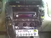
Here's the result (Please excuse the mess... ), pretty clean if you ask me")

And when running

I've been pondering installing a real number voltage gauge in the cab of my Ex for some time now, but I didn't want to use one of my pillar pods for that, nor did I want some giant screen with some logo on it mounted anywhere.
I finally came across this tiny little volt meter on Ebay, so I bought it (Shipped from China)
http://goo.gl/2pEKK
Went down the pick 'n pull and got (2) extra center console tray housings for $7 so I could do some practice cutting.
In the end here's what I did:
- Remove inner tray from bezel
- Mask and mark location for screen penetration.
- Drill hole through center of screen location on bezel.
- Use dremel tool to cut out majority of inner portion.
- CAREFULLY and SLOWLY carve out the rest of the square with a box knife while test-fitting often and making sure not to over-carve.
- Once the hole was cut the screen fit pretty snugly into it (took me 3 attempts to get a cut I was happy with, so I'm glad I bought those extra 2 consoles), the screen was inserted into the hole and I used non-conductive solder ( aka hot glue ) to fill in where the board was offset from the bezel in the back, and to insulate the board itself and tie down the wires.
- The upper flange of the tray piece needed to be ground down a bit, I just carved it out with a box knife to allow room... it's not visible from the front.
- After that, wires were crimped/extended and I added some disconnects so the trim can be removed, then tied it all into the run/aux circuit.
For wiring I already have a start/run and run/aux relays mounted directly below this, so it was easy, but anyone else can do this easy by jumping the radio power lead.
The last piece of the puzzle was to clean up the cut in the bezel (which was close to perfect, just not close enough for my liking). So I went down to the LHS and bought some rubber o-rings in various sizes and found the one that stretched tightly around the screen to clean up the look.
Here's the result (Please excuse the mess... ), pretty clean if you ask me
And when running