Trying to get it right- | Page 2 | Ford Explorer Forums - Serious Explorations

  • Register Today It's free!

Trying to get it right-

My fabbing skills suck-I know this.
I feel my truck doesn't even deserve to be on these pages, where do I start?

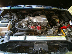
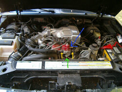
here is the dirty ol thing as it sits now-I'm going in too attempt to address the issues.
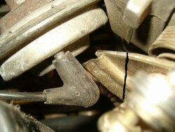
Here is the list

1) leaking valve cover gasket---DONE!
2)oil leaking from fuel pressure guage
3) coilpack bracket needs modding---DONE!
4)intake tube needs fabbed--DONE!
5)throttle bracket fabrication--DONE!
6)wiring clean up--DONE
7) relocate egr stuff-extend wiring to solenoid and dpfe--DONE!
8) fix fuel lines-I don't need them running dual feed-DONE!
9) check lifters-rockers-retorque head nuts--DONE!
10) accessory wiring clean up --DONE!
11) powdercoat everything I can ---ongoing process

Now-this thing has been running fine yes-but if you looked under the hood you might wonder why. Let's see if I can't fix that-or at least improve a bit-
 

Attachments

  • Dirty motor.jpg
    Dirty motor.jpg
    52.6 KB · Views: 796


Join the Elite Explorers for $20 each year.
Elite Explorer members see no advertisements, no banner ads, no double underlined links,.
Add an avatar, upload photo attachments, and more!
.


ok
here is what the bracket is supposed to look like-
The round hole is the throttlecable hole, the other openening is the cruise control cable attachment point-it actually pulls on the throttle cable end which pulls the throttle cable --
 

Attachments

  • cable bracket.jpg
    cable bracket.jpg
    29.3 KB · Views: 330


Join the Elite Explorers for $20 each year.
Elite Explorer members see no advertisements, no banner ads, no double underlined links,.
Add an avatar, upload photo attachments, and more!
.


This is the clearance issue I am having with the throttle "cable hookup" area and egr valve---
I am going to cut it off where the black line is--
Believe me-I have a 94-95 mustang cable and bracket-it won't work--I'm definitely not wrapping a cable there.
 

Attachments

  • tight clearance.jpg
    tight clearance.jpg
    41.9 KB · Views: 340


Now the peadal full pull, and actual WOT

Notice the bottom pic-the cable actually points down-further than current pull angle will allow-but it is close--
 

Attachments

  • pedal pull.jpg
    pedal pull.jpg
    30.4 KB · Views: 310
  • actual full pull.jpg
    actual full pull.jpg
    26.1 KB · Views: 352


You can see I have ac line and egr valve clearance issues--

Here are the bent up--excuse me--
ADJUSTED arms I have to work with
 

Attachments

  • levers.jpg
    levers.jpg
    43.5 KB · Views: 332


weld one back on at an angle-extended outwards also for the 2 cables--

and change the pull angle to more overhead--sorry for the poor picture-you can see where I drew one in on the far right--blck is supposed to represent the cable pulling from upward angle-this is full pedal pull shown so when pedal is let go it will go way back there--

This is the plan-
problem is-this truck is sitting until this is right-that is for sure---
 

Attachments

  • pedal pull modified.jpg
    pedal pull modified.jpg
    30.7 KB · Views: 318


I like the metal tubes so much better and also the overflow tank. These were the first to go in my project. I used a tubular one from a Excavator.


Right now the fuel inlet lines (red circles) fuel y block (blue circle ) and fuel supply lines (yellow) are like this
 

Attachments

  • fuel lines.jpg
    fuel lines.jpg
    69 KB · Views: 311


I'd like to eliminate it all-and run a line straight into the driver side rail ( green line) and a simple crossover line (blue line ) connecting the 2 rails-
pressure should be good like this--
 

Attachments

  • fuel line changed.jpg
    fuel line changed.jpg
    65.9 KB · Views: 318


hmm i think the dual feed is probaily better because you're going to be getting fuel to one rail before the other and when starting up thats not always the best. that and while running it might make one side run lean. i'd suggest the equal length dual feed like it is


hmm i think the dual feed is probaily better because you're going to be getting fuel to one rail before the other and when starting up thats not always the best. that and while running it might make one side run lean. i'd suggest the equal length dual feed like it is

Well, after re reading the instructions

http://www.aeromotiveinc.com/pdf/14102.pdf

It does appear the center port on the bank 1 rail is a return port-not a supply port-
So-I guess they are good the way they are--


Where are the outlet ports of the rail? Do they not usually have ports at both ends at least? Where are the stock fuel line connectors? You should only need to connect each OEM line to one location each on the rails, with the return coming through the FPR.


Jon, I just checked out that PDF link, does your FPR have two inlet ports like that?

Anyway, I see what they have done. There is a T-fitting in both the input and output lines. T-fittings should be avoided(flow), but the two returns at the FPR is okay. I like that they made a separate inlet to each rail, but the T-fitting to split the main line is a poor flow choice.

I have just found a $25 Y-fitting in that Jeg's catalog. I want to use those for trans lines, but that fuel system is what they are ideal for. I would buy on of those Y-fittings and plumb two short lines to the fuel rails. Then plumb the two return lines to the FPR.

Where have you got the FPR, is it near the two OEM lines? I'm interested because I will need to do the same thing with mine. Have you changed the return line to 3/8" line? I'm hoping to do both OEM lines and make more room for headers. Regards,

See, the way I see it if the pressure remains constant clear back at the t-why cant I feed the single rail? I mean-I have 255lph @ whatever pressure I want to adjust for--oh well-
The fuel pressure regulator rides on the coilpack bracket with a pressure gauge mounted in the regulator--a line from each rail to it-then the return line out-- The return line and gauge clear the fan by about 1 3/4 "--lol
I have dual supply and return lines yes-and they are indeed 3/8" returns-
you should be able to see it in the first picture--

BTW do not get a liquid filled gauge-
athough it will steady the needle-the oil leaks out--and it causes another mess-:(


Those Aeromotive instructions recommend replacing the entire return line to the tank, with 3/8" line.

I agree about the inlet to the rails stuff, the stock lines go to just one location. You could do that for anything likely under say 400-450hp. The hard turn at the rail or for the T-fitting is not the best when the horsepower gets a lot higher. With a Y-fitting you could run two short lines straight into the rails at the back. For the front with the FPR at front center I'd run two more lines from the rails straight forward to the FPR. How would that lay in there?


I only used about 10" of the 45 elbow-but that's ok, I'll be needing the pipe for my exhuast.
Now-on to the throttle bracket--:confused:
Rocket said he'd make me one up-but need my throttle body for a while-
I'm trying to get this all done this weekend if possible--


Answer your emails Jon. I have Jim's throttle cable bracket done. Now that I have my design set in place yours will be literally maybe an hour or two to make if that. Just a little cutting, bending, drilling tapping and welding...


Here is a pic or two of what I did for Jim's X. I still have some prettying up to do but that is it right there.
 

Attachments

  • Jims TB Cable Pics 009.jpg
    Jims TB Cable Pics 009.jpg
    51.2 KB · Views: 308
  • Jims TB Cable Pics 011.jpg
    Jims TB Cable Pics 011.jpg
    109.1 KB · Views: 307


Also, DO NOT CUT that top arm off your TB! That will be the best and only location to realistically mount your new ball socket to. If you cut that off then you will have a fun time welding that craptastic metal back together. You will instead heat and bend that metal arm straight to give you more room to move away from the point of rotation on the TB arm. That will still give you full pull, but not so much of a camming affect where you have an ultra-sensitive gas pedal. Shoot me a email sometime and I can give you the exact distance that the ball has to be away from the point of rotation.


attachment.php


Join the Elite Explorers for $20 each year.
Elite Explorer members see no advertisements, no banner ads, no double underlined links,.
Add an avatar, upload photo attachments, and more!
.


I like the look of this intake set-up. I can already see the finished results.


Back
Top