xcbuc
Member
- Joined
- November 23, 2009
- Messages
- 11
- Reaction score
- 0
- City, State
- Portage,WI
- Year, Model & Trim Level
- 2005 Eddie Bauer 4x4 XLT
My girlfriend’s alternator went out so I decided to tackle this project. I researched this quite a bit and found it was going to be a huge pain. I’ll agree to that after it was installed. I found some useful information online and learned some tricks along the way. I wanted to break it down even further for everyone that attempts this. I’ve taken a lot of that information and took some pictures along the way to help others. Just want to say thanks for original help I got from discussion boards. Thanks jpark for the actual alternator install instructions on escape-central.com. I also replaced my ball joint and ABS tone ring. I listed those how-to's as well.
http://wiki.answers.com/Q/How_do_you_replace_the_front_wheel_bearing_on_a_2003_Ford_Escape##
Tools
- PB Blast Everything thing a couple minutes ahead of time
-32 MM Axle Nut Socket
- Ratchet Handles & Sockets (At least 18mm & ¾”)
- Pliers for removing cotter pins
- Shop Light
- Screw Drivers
- Couple Vice Grips
- Dead blow hammer (4# sledge)
- Jack & at least 1 jackstand
- Torque wrench that can go to 140 ft lbs
- high quality grease
- bungee cord/zip ties (for brake caliper to hang)
- Brake Cleaner
- Plenty of Rags/Towels
- Block of wood / or a brass hammer
Things that come in handy
- Beer
- Patience
- Door Clip Remover
- 2 Jaw Gear Puller
- Double Flex Quick-Release ratchet or an angled extension
- Electric or Air Impact gun
- Blow Torch for help removing stubborn bolts
- Something to kneel on
- Pipe or something similar to act as a lever on the end of the ratchet handles
-Someone to help
1. Disconnect battery. Important!!
2. Jack up vehicle and place it on jack stands.
3. Remove front wheel and remove the black plastic splash shield from underneath the right side of the engine. It's held on by about 5 M8 bolts, and one Phillips head screw. Be careful the front M8 bolt may be rusted and break.
4. Remove the serpentine belt. Insert a ½” drive socket into the tensioner pulley. Rotate the drive belt tensioner. This will take the tension off the belt. You must hold the pulley and unloop the belt at the same time. Remove the belt now.


5. Your goal here is to remove the axle that is in the way of the alternator. Some people leave the ball joint attached to the steering knuckle and others detach it. I wanted to replace my ball joint while I was there so detached it. For people that want to leave it on, probably easier forget the ball joint process. I was able to leave my lower control arm connected though when I did it this way. I did have to take off my tie-rod though. There is the castle nut and retaining pin to take your tie-rod off.
a. Loosen but to not remove the 32mm nut that holds the axle half-shaft to the spindle. I bought one from Autozone for $10. Back the nut off so about half the threads can be seen- you will hit the head of the nut to get it to go back through the spindle. You will take it off completely later.


b. Remove brake caliper. There are 2 bolts on the back of the caliper. I used zip ties to hold it to the top of the shock/strut.
c. Remove bottom ball joint pinch bolt and nut. You MUST totally remove the pinch bolt because the ball joint is hour-glass shaped. This bolt is usually pretty rusty. It can be a pain to remove. First remove the nut. Then use a hammer and punch to push the bolt out.

d. You must now detach the steering knuckle from the ball joint. This is tricky. Due to the angle of the ball joint it might not want to come out. You can take a chisel and separate where the pinch bolt and nut meet. Or another method is on another site. Check out the videos that Ivon5401 put together for help. http://www.escape-central.com/1forum/showthread.php?s=&threadid=34714

e. Remove lower control frame.(I left mine attached, Others removed it). There are 2 bolts. Remove the front (15mm) and rear (3/4") bolts holding the lower control arm to the frame. You can now swing the whole assembly away.
f. Finish taking off the nut that attaches the axle to the knuckle/spindle. Take wheel hub nut off completely. You want to force the axle out of the spindle/bearing. You can hit it with a hammer to force it out. You can also use a 2 jaw gear puller.

Out.

g. Now you that you have the front part of the axle/halfshaft out, there are 2 nuts holding the inner side of the axle by the transmission. Remove them. Sorry for the picture but the axle is out and the 2 nuts are general locations. You get the idea though. Once you have the nuts out you can pull the entire axle/half shaft out. Do it as one whole unit. If the vehicle is jacked up level on each side, be careful of the transmission fluid coming out. Get a small bucket ready if it does come out. My truck was jacked at an angle so none came out.

6. Remove the back splash guard . There are 2 plastic snap clips holding it. I used a door clip remover. I love this tool. If they break replace them. They are cheap and at any automotive store.

7.You must first remove the 3 bolts holding the alternator to the bracket. There are 2 bottom bolts and 1 on top. The 2 bolts are referenced in the picture. These are pretty long. I recommend a Double Flex Quick-Release ratchet or an angled extension. This will make getting the top one out easier. You can angle the head of the socket for better accessibility.
Bottom

Top

10. Take out the alternator bracket. There are 3 bolts that hold it. The top one can be trickier. Déjà vu again?

11.You must now rotate the alternator to gain access at the wire connector and wire harness. I rotated it gain better access. The wire connector can be pried out. Be careful with the regulator connector, you need to push in the tab that holds it in. I used a flat screw driver on the bottom of the tab to release the snap lock. (Look at the new alternator and you will see a little square hole in the mating connector on the alternator where this snap lock engages the connector. This holds the connector on.) The wire eye terminal is held on by a nut.

12. You can finally take out the alternator. It goes out in between the hole in the picture. That sounds easier said then done like anything else here. You have to twist the alternator around and try different angles to get it out. Probably a lot of cursing going on here! If they would have given vou another ¼” it would come out so easy.
13. Now time to install the alternator. It takes a little time to rotate the alternator in the small space you took it out. Just remember it will go in!!
14. Connect the eye terminal and wire connector.
15. Install alternator mounting bracket. 3 bolts.
16. Install alternator to mounting bolts. 3 bolts.
17. Install alternator splash guard using clips. Might have to replace some if you broke some.
18. Install axle. When seated properly, the halfshaft bearing retainer circlip will snap into the differential side gear groove. Position the halfshaft and joint so that the splines align with differential side gear splines. Push the halfshaft into side gear. Align and tighten the 2 bolts that hold the inner axle.
19. Install serpentine belt. Reference picture above or this one. Remember groove in belt goes to groove on pulley. Smooth part of belt goes to smooth part on pulley/ tensioner.

20. Install splash guard.
21. Install lower control arm. 2 bolts.
22. Maneuver the axle shaft through the wheel bearing.
23. Re-attach the pinch joint and install the bolt in the joint. You may have to move the lower control arm up and down until the bolt will go through. I had trouble with mine. I used a chisel and pushed the 2 parts of the knuckle where the pinch bolt goes into. Then just hammer it down. This opened it up enough for me to insert the knuckle onto the pinch bolt. Once the bolt is back in place, tighten it to 52 ft/lbs
Note: I forgot to take a picture of the Escape steering knuckle. I found this one online and used it to reference where you need to open the 2 parts where the pinch bolt goes through. It makes life easier putting it back on.

24. Put the axle bolt on the 1/2 shaft and hand tighten snugly
25. Re-attach the tie rod end and tighten the castle nut to 41 ft/lbs
26. Put the rotor back on.
27. Re-mount the caliper bracket and tighten those bolts to 111 ft/lbs using torque wrench part number 67075 (above).
28. Re-mount the caliper and brake pads. Tighten the caliper mounting pins to 26 ft/lbs
29. Mount the tire. Tighten the lug nuts to 98 ft/lbs
You can lower the truck now.
30. FINALLY, using the torque wrench, tighten the axle nut to 205 ft/lbs
31. Hook battery back up.
32. Check tranny fluid if you lost some.
Should be good to go then!! It is quite the project for a small piece. Good luck to all. Feel free to add anything I missed after I put this together. Or other tips or tricks. Keep a weekend open for this project in case you break anything or take longer then expected.
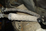
ABS Tone Ring
Tools
-Torch
-Punch
-ABS Tone Ring (Autozone or any autoparts store)
I also had a broken abs tone ring. It connects to the end of the axle/half shaft. It’s a very common problem for these vehicles. This is the abs light that stays on in your dash. You can see it from the picture that it is broke. I listed the vague steps of it. The in depth install can be found here. It is on a Ranger but the Tone Ring was the same. http://www.therangerstation.com/forums/showthread.php?t=85395
Or
http://www.escape-city.com/viewtopi...7853&hilit=rear+tone+rings+replacement#p87853

1. You must take the screw holding the abs sensor off the knuckle. Loosen 8mm bolt holding in ABS sensor. You can then pry out the sensor from the knuckle.
2. Clean the rust off the area on the axle where the tone ring mounts. I used a sanding roll on a die grinder but a wire brush would probably work as well.
3. Tap the new tone ring into place using a brass hammer and a punch. Take your time and keep the ring straight as it goes on. Make sure it goes on all the way to the shoulder on the axle.
4. Assemble everything in reverse order and you'll be good to go. The ABS light went out instantly. The 4WD light stayed on for about two miles before the PCM realized that it was fixed.
Ball Joint
Tools
-Ball Joint Press (Can be rented at Autozone, $100 desposit but get all of it back when you return it)
-Snap Ring Pliers
-Grease
I found that the Escape’s lower ball joint was opposite of what a lot of Fords are. The spindle/arm of the ball joint is positioned to the top through the lower control arm. A lot of vehicles have the spindle/arm facing downward. This confused me when I went to take it out. I borrowed some pictures similar to the Escape. I also did the ball joint with the lower control arm attached. It might be easier with it out.
1. Remove worn ball joint boot using the end of the flat head screwdriver

2. Clean off ball joint surface with a shop towel.
3. You now need to assemble ball joint press pushing the ball joint down through the LCA. You will have to look at the different parts to get it right. If you do it the wrong way, it wont budge. It might be tricky to get it where the ball joint arm stays straight. With the press on it, it will want to move to the side. You will hear a popping sound when it starts to go.


4. Once assembled use your 7/8" socket and 1/2" drive ratchet/breaker-bar/impact to tighten the press down on the ball joint

5. Continue to tighten; the ball joint will begin to slide out of the LCA
6. Once the ball joint is free, it'll all probably fall the to the floor...like so.
Time to Install
1.Install the ball joint from the underside of the LCA

2.Assemble the press so that it pushes the ball joint up through the opening in the LCA.

3.Tighten press using impact gun, 1/2" ratchet, or breaker bar
Continue to tighten the press and make sure the ball joint installs straight and completely into the arm. Mine was a little loose on the bottom. I need to hit the bottom side of lower control arm to force pressure onto the ball joint bottom. Make sure the bottom(not arm) of the ball joint does not move at all.

4.Install included snap ring using snap ring pliers.

5.You can now insert the ball joint boot. The bottom ring of the boot should fit into the other top groove on the ball joint.
6. Insert and tighten grease zerk on bottom.
7. Grease zerk.
http://wiki.answers.com/Q/How_do_you_replace_the_front_wheel_bearing_on_a_2003_Ford_Escape##
Tools
- PB Blast Everything thing a couple minutes ahead of time
-32 MM Axle Nut Socket
- Ratchet Handles & Sockets (At least 18mm & ¾”)
- Pliers for removing cotter pins
- Shop Light
- Screw Drivers
- Couple Vice Grips
- Dead blow hammer (4# sledge)
- Jack & at least 1 jackstand
- Torque wrench that can go to 140 ft lbs
- high quality grease
- bungee cord/zip ties (for brake caliper to hang)
- Brake Cleaner
- Plenty of Rags/Towels
- Block of wood / or a brass hammer
Things that come in handy
- Beer
- Patience
- Door Clip Remover
- 2 Jaw Gear Puller
- Double Flex Quick-Release ratchet or an angled extension
- Electric or Air Impact gun
- Blow Torch for help removing stubborn bolts
- Something to kneel on
- Pipe or something similar to act as a lever on the end of the ratchet handles
-Someone to help
1. Disconnect battery. Important!!
2. Jack up vehicle and place it on jack stands.
3. Remove front wheel and remove the black plastic splash shield from underneath the right side of the engine. It's held on by about 5 M8 bolts, and one Phillips head screw. Be careful the front M8 bolt may be rusted and break.
4. Remove the serpentine belt. Insert a ½” drive socket into the tensioner pulley. Rotate the drive belt tensioner. This will take the tension off the belt. You must hold the pulley and unloop the belt at the same time. Remove the belt now.
5. Your goal here is to remove the axle that is in the way of the alternator. Some people leave the ball joint attached to the steering knuckle and others detach it. I wanted to replace my ball joint while I was there so detached it. For people that want to leave it on, probably easier forget the ball joint process. I was able to leave my lower control arm connected though when I did it this way. I did have to take off my tie-rod though. There is the castle nut and retaining pin to take your tie-rod off.
a. Loosen but to not remove the 32mm nut that holds the axle half-shaft to the spindle. I bought one from Autozone for $10. Back the nut off so about half the threads can be seen- you will hit the head of the nut to get it to go back through the spindle. You will take it off completely later.
b. Remove brake caliper. There are 2 bolts on the back of the caliper. I used zip ties to hold it to the top of the shock/strut.
c. Remove bottom ball joint pinch bolt and nut. You MUST totally remove the pinch bolt because the ball joint is hour-glass shaped. This bolt is usually pretty rusty. It can be a pain to remove. First remove the nut. Then use a hammer and punch to push the bolt out.
d. You must now detach the steering knuckle from the ball joint. This is tricky. Due to the angle of the ball joint it might not want to come out. You can take a chisel and separate where the pinch bolt and nut meet. Or another method is on another site. Check out the videos that Ivon5401 put together for help. http://www.escape-central.com/1forum/showthread.php?s=&threadid=34714
e. Remove lower control frame.(I left mine attached, Others removed it). There are 2 bolts. Remove the front (15mm) and rear (3/4") bolts holding the lower control arm to the frame. You can now swing the whole assembly away.
f. Finish taking off the nut that attaches the axle to the knuckle/spindle. Take wheel hub nut off completely. You want to force the axle out of the spindle/bearing. You can hit it with a hammer to force it out. You can also use a 2 jaw gear puller.
Out.
g. Now you that you have the front part of the axle/halfshaft out, there are 2 nuts holding the inner side of the axle by the transmission. Remove them. Sorry for the picture but the axle is out and the 2 nuts are general locations. You get the idea though. Once you have the nuts out you can pull the entire axle/half shaft out. Do it as one whole unit. If the vehicle is jacked up level on each side, be careful of the transmission fluid coming out. Get a small bucket ready if it does come out. My truck was jacked at an angle so none came out.

6. Remove the back splash guard . There are 2 plastic snap clips holding it. I used a door clip remover. I love this tool. If they break replace them. They are cheap and at any automotive store.
7.You must first remove the 3 bolts holding the alternator to the bracket. There are 2 bottom bolts and 1 on top. The 2 bolts are referenced in the picture. These are pretty long. I recommend a Double Flex Quick-Release ratchet or an angled extension. This will make getting the top one out easier. You can angle the head of the socket for better accessibility.
Bottom
Top
10. Take out the alternator bracket. There are 3 bolts that hold it. The top one can be trickier. Déjà vu again?
11.You must now rotate the alternator to gain access at the wire connector and wire harness. I rotated it gain better access. The wire connector can be pried out. Be careful with the regulator connector, you need to push in the tab that holds it in. I used a flat screw driver on the bottom of the tab to release the snap lock. (Look at the new alternator and you will see a little square hole in the mating connector on the alternator where this snap lock engages the connector. This holds the connector on.) The wire eye terminal is held on by a nut.
12. You can finally take out the alternator. It goes out in between the hole in the picture. That sounds easier said then done like anything else here. You have to twist the alternator around and try different angles to get it out. Probably a lot of cursing going on here! If they would have given vou another ¼” it would come out so easy.
13. Now time to install the alternator. It takes a little time to rotate the alternator in the small space you took it out. Just remember it will go in!!
14. Connect the eye terminal and wire connector.
15. Install alternator mounting bracket. 3 bolts.
16. Install alternator to mounting bolts. 3 bolts.
17. Install alternator splash guard using clips. Might have to replace some if you broke some.
18. Install axle. When seated properly, the halfshaft bearing retainer circlip will snap into the differential side gear groove. Position the halfshaft and joint so that the splines align with differential side gear splines. Push the halfshaft into side gear. Align and tighten the 2 bolts that hold the inner axle.
19. Install serpentine belt. Reference picture above or this one. Remember groove in belt goes to groove on pulley. Smooth part of belt goes to smooth part on pulley/ tensioner.
20. Install splash guard.
21. Install lower control arm. 2 bolts.
22. Maneuver the axle shaft through the wheel bearing.
23. Re-attach the pinch joint and install the bolt in the joint. You may have to move the lower control arm up and down until the bolt will go through. I had trouble with mine. I used a chisel and pushed the 2 parts of the knuckle where the pinch bolt goes into. Then just hammer it down. This opened it up enough for me to insert the knuckle onto the pinch bolt. Once the bolt is back in place, tighten it to 52 ft/lbs
Note: I forgot to take a picture of the Escape steering knuckle. I found this one online and used it to reference where you need to open the 2 parts where the pinch bolt goes through. It makes life easier putting it back on.
24. Put the axle bolt on the 1/2 shaft and hand tighten snugly
25. Re-attach the tie rod end and tighten the castle nut to 41 ft/lbs
26. Put the rotor back on.
27. Re-mount the caliper bracket and tighten those bolts to 111 ft/lbs using torque wrench part number 67075 (above).
28. Re-mount the caliper and brake pads. Tighten the caliper mounting pins to 26 ft/lbs
29. Mount the tire. Tighten the lug nuts to 98 ft/lbs
You can lower the truck now.
30. FINALLY, using the torque wrench, tighten the axle nut to 205 ft/lbs
31. Hook battery back up.
32. Check tranny fluid if you lost some.
Should be good to go then!! It is quite the project for a small piece. Good luck to all. Feel free to add anything I missed after I put this together. Or other tips or tricks. Keep a weekend open for this project in case you break anything or take longer then expected.
ABS Tone Ring
Tools
-Torch
-Punch
-ABS Tone Ring (Autozone or any autoparts store)
I also had a broken abs tone ring. It connects to the end of the axle/half shaft. It’s a very common problem for these vehicles. This is the abs light that stays on in your dash. You can see it from the picture that it is broke. I listed the vague steps of it. The in depth install can be found here. It is on a Ranger but the Tone Ring was the same. http://www.therangerstation.com/forums/showthread.php?t=85395
Or
http://www.escape-city.com/viewtopi...7853&hilit=rear+tone+rings+replacement#p87853
1. You must take the screw holding the abs sensor off the knuckle. Loosen 8mm bolt holding in ABS sensor. You can then pry out the sensor from the knuckle.
2. Clean the rust off the area on the axle where the tone ring mounts. I used a sanding roll on a die grinder but a wire brush would probably work as well.
3. Tap the new tone ring into place using a brass hammer and a punch. Take your time and keep the ring straight as it goes on. Make sure it goes on all the way to the shoulder on the axle.
4. Assemble everything in reverse order and you'll be good to go. The ABS light went out instantly. The 4WD light stayed on for about two miles before the PCM realized that it was fixed.
Ball Joint
Tools
-Ball Joint Press (Can be rented at Autozone, $100 desposit but get all of it back when you return it)
-Snap Ring Pliers
-Grease
I found that the Escape’s lower ball joint was opposite of what a lot of Fords are. The spindle/arm of the ball joint is positioned to the top through the lower control arm. A lot of vehicles have the spindle/arm facing downward. This confused me when I went to take it out. I borrowed some pictures similar to the Escape. I also did the ball joint with the lower control arm attached. It might be easier with it out.
1. Remove worn ball joint boot using the end of the flat head screwdriver
2. Clean off ball joint surface with a shop towel.
3. You now need to assemble ball joint press pushing the ball joint down through the LCA. You will have to look at the different parts to get it right. If you do it the wrong way, it wont budge. It might be tricky to get it where the ball joint arm stays straight. With the press on it, it will want to move to the side. You will hear a popping sound when it starts to go.
4. Once assembled use your 7/8" socket and 1/2" drive ratchet/breaker-bar/impact to tighten the press down on the ball joint
5. Continue to tighten; the ball joint will begin to slide out of the LCA
6. Once the ball joint is free, it'll all probably fall the to the floor...like so.
Time to Install
1.Install the ball joint from the underside of the LCA
2.Assemble the press so that it pushes the ball joint up through the opening in the LCA.
3.Tighten press using impact gun, 1/2" ratchet, or breaker bar
Continue to tighten the press and make sure the ball joint installs straight and completely into the arm. Mine was a little loose on the bottom. I need to hit the bottom side of lower control arm to force pressure onto the ball joint bottom. Make sure the bottom(not arm) of the ball joint does not move at all.
4.Install included snap ring using snap ring pliers.
5.You can now insert the ball joint boot. The bottom ring of the boot should fit into the other top groove on the ball joint.
6. Insert and tighten grease zerk on bottom.
7. Grease zerk.