I dissagree you should "try" to fix the pinion angle.

The sharper the pinion angle becomes, the more stress on the u-joint and also the more the driveshaft gets pulled out of the tranny.
[Pulls out the geometry book and blows the dust off ..]
Ok say we have a hypothetical Explorer scaled down (for simplicity) where the drive shaft is 5 feet long, and a section of the frame is 4 feet long and the height from the frame to the differential is 3 feet high.
So we have a right triangle.
Frame 4'
---------------------
- |
- | Diff height 3'
Drive Shaft 5' - |
- |
So if we use the formula c^2 = a^2 + b ^2 (Pythagorian sp?)
5*5 = (4 * 4) + (3*3)
25 = 16 + 9
25 = 25
We know that this triangle is correct.
If we do a SOA and put the leaf on top of the axle we're going to add 3.25" + the thickness of the perch + the thickness of the leaf pack.
We'll say the the axle tube is 3.25", the perch is 0.5", and the leaf pack is 1.0" for a total of 4.75".
Converting that into feet: 4.75"/12"= .3958'
New frame to diff height: .3958' + 3'= 3.3958'
So if we plug into the formula a (the fixed frame section length) 4' & the new frame to diff height 3.3958', we now solve for the new driveshaft length.
c^2 = (4*4) + (3.3958*3.3958)
c^2 = (16) + (11.531)
c^2 = 27.531
c = 5.247'
So the difference is 0.247' which converted & rounded off is 3", if my math is correct.
Therefore if you do a hypothetical SOA, you need a 3" longer driveshaft.
By rotating the diff up, you may be able to regain a precious inch of driveshaft. I'c drank too much to do the math on that right now plus that's way too much for my old ass to do.
Oh yeah, don't for get to paint them too.
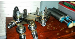
Just found this on my site. Click the link, then right click the image & then click play. The red thing is a perch.
> Animation