Wiring Project (has pics :-)) | Ford Explorer Forums - Serious Explorations

  • Register Today It's free!

Wiring Project (has pics :-))

SwaintaN

Explorer Addict
Joined
March 15, 2008
Messages
2,348
Reaction score
2
City, State
Carey, Ohio (Georgia Grown)
Year, Model & Trim Level
93 XLT
Ok, so wanting to clean/replace some wires under the hood. (this is taking me back to my car audio days).. was wondering if we couldnt use Distribution Blocks to eliminate wire to the battery terminals give it a more cleaner and professional look.

Untitled.jpg


Join the Elite Explorers for $20 each year.
Elite Explorer members see no advertisements, no banner ads, no double underlined links,.
Add an avatar, upload photo attachments, and more!
.


Not sure where you would put the blocks... I have been thinking about doing the headlight harness deal, and I don't even know where to put 2 relays.

Your diagram, well, I'm sure you are thinking about this too, whether to run the alternator to the battery or positive block. I'm trying to go through the different charge/discharge/use scenerios and... let me think a while longer.

Ok... so, if you are going for the big cable look, or happen to have a supply of cheap #0, then what you have will work great. A more efficient way would be to run the alternator to the positive block with #2, and use #1 from the battery to the block. If you are going to be running high current accessories, you could use #1 on the alternator.

In a tight engine bay, I would probably go up one wire size all around due to heat-driven resistance. It appears you have plenty of airflow, though.


I went out and looked at the engine bay, what all i would need and lay out space... this is my positive lay out that i am gonna follow
PosLayOut.jpg


and this would be the negative lay out..
NegLayOut.jpg


Ive gotten rid of the A/C components so some of the air will flow better. engine bay doesnt seem to get to hot and all wires and parts are name brand. ive already got about 30 ft of 4 ga wire and friend of mine can get 0 ga for pretty cheap.. all ill have to do is where terminals need to go are buy terminals and solder

the db are water proof, rust proof etc...


#4 for the starter is borderline small...

You need to fuse > than your alternator output. As it is, if the battery were dead and you jump started it, your alternator would try to dump 150A into the battery and blow that 100A fuse. I would put 200A fuse there.

I don't think I would use those 'T's unless I had a definite need for them. Every connection is a failure point.

I guess I'm also wondering if you are planning to solder 0 GA wire. I guess not, just curious, it would be difficult.


Ok explain the fuse to me, im sorry i kinda was going by car audio style, where the fuse had to be less so it wouldnt blow up what it was connected to, but amps get power from battery not send power to battery.. so i guess i can understand that one


4ga to the starter is stock, im just rerunning it with a newer better 4ga wire.

ive soldered 0 ga wire before, not to bad, just a lil more solder and heat is all


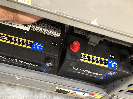
Fuse, yes, you are on the right track. A perfectly functional 140A alternator can generate... up to 140Amps. So, you have to fuse for that much because a dead battery will take all of that load. Rule of fuses is to oversize by 25% or so... 200Amp.

See, what you are really guarding against is this cable shorting to ground, either at the alternator terminal, or somewhere along the way. If that were to happen, that would be a dead short across the battery and that is, of course, bad news. I'd put the fuse as close to the battery as reasonably possible.

If the engine were running and that cable shorted, the fuse blows, so no shorted battery, but you still have a shorted alternator. Hmm... well, the original design puts a fusible link at the starter relay, which is at the battery.
Try not to short the cable if the engine is running.


see i was thinking of car audio when i did 80amp anl fuse instead of higher then alternator output, but as i was thinking about after you talked about it, i guess i get it, because alternator supplies power to the battery, so the fuse protects the battery, like an amp gets power from the battery so the amp is protected with its fuse, ok that makes sense.

yes the original wire from alt went to the starter solenoid on the fender with a fusible link, my original fusible link is damaged... but when you do the big 3 upgrade it says take the alt directly to the battery with an line fuse. so when my new anl fuse holder gets here ill get a 200 amp fuse instead, awesome!

this is why i joined the forum and keep paying for elite membership, cause in long run this forum saves me lots of money!


My friend is getting me the parts (he gets them under cost) so its a slow process... however he did get me the 0 gauge Cadence Wiring and 0 Gauge Stinger Terminal and EFX ANL fuse holder... shoo soo alternator is done..


You can see the set up, how short the wire is from ANL to battery... about 3"
AltANLBattery.jpg


Night Shot.. it has Digital Read out on it... after sitting for about a week not started, it started right up... and settled at about 14.5, the pic shows 13.9 but i turned on the Radio..
AltANL.jpg


Oh Yeah, the 0 Gauge Terminals are soldered on, not crimped, solder holds better and better connection.


So got the Alternator done (now alt is hot to touch). Friend got me all the stuff I needed to finish up. The gold plated DB, about 20 ft of 4ga wire, 4ga terminals, 0 ga wire, 0ga terminals, now just need to get off my lazy butt and put it together.. hoping to have it done and be looking good


Back
Top