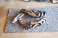
These are the parts I picked up total cost for all ( t-case including motor, fuel tank and d-shafts, 290 bucks!!)
Here 93 switch that is being sacrificed for the plug on the back I need it to modify the new switch as the new switch doesn't work as I thought so I must modify it to work
Cutting the back up to make room for the harness
Here is the ford pcb(printed circuit board that will not work for my design , the switch and the old harness/clip
Finally got the clip free of the surrounding plastic
Had to modify the back alittle more so the pins on the harness will actually reach the pcb so they can soldered in
Finished case a little hot glue and it fits perfectly,
copper laminate prep'd for the pcb layout

images must be printed by a toner printer as this method of printing uses plastic this is the key ingredient in making the pcb work, make the design in a pcb software, inverse the image and print on photo paper, then place the paper on your laminate sheet with the toner side facing the copper and the transfer the toner with the heat of an iron, once transferred the toner will now act as an etch resist. This works perfectly because the circuit can then be dipped in ferric chloride a common etch resist, you can buy at radioshack and the uncovered copper will be eaten away leaving only whats covered under the toner intact. If you need to make touch ups say the toner didn't transfer as well as you hoped then a regular sharpie marker works great, apply heavily and let dry and it works once board is done being etched, rinse in water to stop process and rub off etch resist with nail polish remover, cut to size, drill holes and you've got yourself a homemade pcb, good enough to piss your friends off with envy!!

Ironing, aka transferring toner to laminate
soaking in ferric chloride
rough finished product, this is the old circuit I jumped the gun and made it before I tested the shift motor circuitry, shift motor works differently so I had to design a new circuit, this is for illustrative purposes
shift shaft, rotates from 2H to 4H to 4L and then to either for to 4H or 2H motor must reverse polarity and travel in the opposite direction, had to redesign circuit to allow for motor polarity change DPDT relays are great! Good news is though doing it this way I won't have to design a pcb for the position sensor as the ford one will work! more on that down further
Marked shift motor and subsequently the position sensor for some experimenting to figure out the internal circuitry which much to my dismay is inaccessible, so ingenuity had to lead the way out comes the multi meter and about 30 min of testing!
position sensor
Marked on the back side following shift motor, allowed me to figure out the circuits and the sensor is also adjustable on the body so it will work great!
I figured out that Yellow is constant 12V in and for two high the sensor has continuity between yellow and white in all positions except 2H so this is the 2H signal wire, 4L is yellow and brown, in which brown has continuity with yellow ie 12v to power the shift motor relay circuitry in all positions except 4L which is great because as soon as motor sensor hits 4L position is looses continuity and shuts the motor down at the right time, (remember earlier this is why it is great that the sensor is adjustable!)
4H is a little different, 2H and 4L are the only positions that require one direction of travel albeit different directions they only need one,
In 2H or 4H if you select 4L the motor only travels one way to reach it and that is the last position it can travel it doesn't not need to change directions to reach as the same is for the 2H circuitry, think about it.
4H can be accessed from either 4L or 2H so the motor must be capable of two directions of travel in this case, so the sensor must pick up where the motor actually is, from 4L to 4H the motor must travel to the right i.e., yellow has continuity with orange, upon arrival to 4H orange loses the 12V signal shutting the motor down if 4H is selected from 2H the motor must travel in the opposite direction i.e., yellow has continuity with purple, upon arrival same thing,
This is why I had to redesign my circuit, as I planned on the shift shaft only needing to travel in one direction,
An additional relay and a DPDT relay and we've got it baby
this is the circuit I came up with to handle the shifting duties, works in theory however DPDT relay is still in the mail so I'll have to wait to test it when it comes in
This is the circuit drawn up in PCBExpress, did all the calculations to figure line thickness v. amperage capacity, amazingly when I bench tested the motor and t-case it only drew 1.5 amps max at 12.8 volts! so the circuit can handle 5 amps so should be plenty
This is the slightly finished product still waiting on the DPDT relay
Don't hate the soldering but some of these lines are really close and if I have to do it again I will keep that in mind...
 maybe smaller than the GEM itself...