410Custom's builds a 2007 Ranger V8 - custom truck build - Project "Ranger Premier" | Page 36 | Ford Explorer Forums - Serious Explorations

  • Register Today It's free!

410Custom's builds a 2007 Ranger V8 - custom truck build - Project "Ranger Premier"


Join the Elite Explorers for $20 each year.
Elite Explorer members see no advertisements, no banner ads, no double underlined links,.
Add an avatar, upload photo attachments, and more!
.


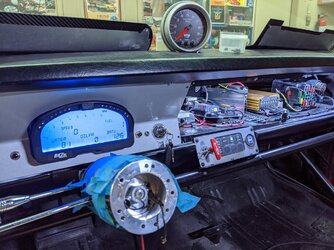
Started taking an 07 instrument cluster apart, there is little hope of modifying the fixture
However it is possible to hack the cluster, it is happening more and more in the world of can bus clusters
I did some researching and reading yesterday, this is something I am looking into

In other news the truck is running! But I am still out of time with the cam synchro
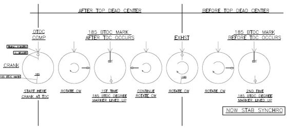
I made a chart to show where the cam synchro should be stabbed
My new friend over at classicbroncos has taken the time to school me 100% in this issue and now I fully get it!
The synchro must be stabbed at 185 degrees before top dead center occurs
Like this
crank timing how to 09242022.jpg


I am going back and fixing the original post on the crank balancer to show this. (Basically I needed to go around one more time)
I will be Re stabbing the synchro today

Also the Hall effect crank sensor came in from lowdollar motors. So I fabricated a simple mount using stock parts (dirty parts!)
5B7EC559-A6C5-4F4E-939A-AB37EA7D785E.jpeg

Parts needed cleaned they came off a low mile engine I have in. The shop, but a nasty messy engine at that! I also used same engine for mock up
8DD408AE-3FDE-4712-81A6-339E58C29CF9.jpeg

Had no idea the factory guard said “time” on the pointer learn something everyday
ED325AF1-505A-408B-A46C-6C4EA630AB10.jpeg


Now to make a simple jig, this ensures the new sensor lands in exact location as stock sensor
C1ADD658-8973-4A2E-832A-A9080DD034E5.jpeg

310B269A-37F9-4595-93E6-3776C0BE3595.jpeg

Sensors location in relation to the mounting screws is what I was interested in
820A8AB9-FCC8-42A7-81FB-3BBE59345EC2.jpeg

Cut simple piece of metal and welded in proper
Location
31241AC2-942F-4BCE-83F8-93690B3EC10A.jpeg

6A7FCBB2-C4AE-49E9-8F26-F94837AC5FCF.jpeg

F7A200E1-AE22-4ADC-8A59-4FD462DEDBFA.jpeg
crank-timing-how-to-09242022-jpg.jpg


AA665094-FBB6-450D-ABB2-BC6BD592F877.jpeg


EFA552D7-30F2-4581-AF45-D6444E42D322.jpeg


ACA7AD79-4333-44C3-9E57-ED157334CDD3.jpeg

09592D7B-AA7D-4B46-98E5-E432F906C57C.jpeg

Perfect!!
Now to install I will have to tap into the power feed for the cam synchro and run to this sensor as well
Old sensor two wires ground from pcm and signal to pcm
New wires pcm ground, pcm signal and clean power
Holley software make simple change for new hall effect crank sensor and we are rolling
E7455436-032F-43C7-BCF9-5712A96D2C5D.jpeg


I then took a 07 cluster apart to see about potential hacking ( and I mean hacking with soldering iron and hot knife)
Looks difficult w these clusters
So looking into hacking the software side of things
8C4C192D-9E74-4B0B-BA1C-B4C426A451A4.jpeg

B55FEAD7-A104-4440-9AE8-5D83B0A31002.jpeg

46ACA6DC-9163-47D6-9C1A-0A9E5DDA697A.jpeg

The needles won’t even come off with a fork like the old ones did shoot

79E8D9C0-9595-4574-A4D1-FED9A5779977.jpeg

A4773CCB-3053-48D5-97D5-F669A3F4F181.jpeg

This will be an on going project as I finish the rest of the truck

9B688C39-8DBA-460B-A647-3DC71AF1B9B2.jpeg

CE6234BF-8295-46D0-83D9-CC8DE8C0DC5A.jpeg


Easy to adjust! I am able to fit a wrench on the front and backside
I adjusted it on a spare engine though so I won’t have to in the truck


Some people use the stock ecm to control the factory gauges.


I am not interested in a piggyback! (If we can help it)
Already too late I have been busy
As cool as hacking can bus clusters is wicked potential for resto mods and drivetrain conversions I already have a factory based solution :) I will have to run some wires…
We are keeping a factory cluster and adding to it!
I will likely need a Dakota box for the speedo signal
I need to locate a tach signal from the Holley


So as you guys know I have several dashboards in the shop for this project
While messing with the 07 cluster and the wiring to it I had a question pop into my head, do any of these other late model clusters have additional wires for the indicator lights? Sure enough the 05 dash I have has a cluster that looks similar, but guess what about 30 wires instead of 15!

05 cluster
?hash=ecd88e05eb3e62fbdbfb909c40e8b9e7.jpg


07 cluster wiring
97B0753D-79ED-4890-B909-4904F29F99D3.jpeg


So out come the wiring books to confirm. Sure enough the 05 cluster still has Can Bus connections BUT it also has all the wires for the gauges and indicator lights! So my plan is to use the guts from an 05 cluster and the face of the 07 cluster that came with the truck
I will likely need a Dakota digital interface to get the signal needed for the speedometer, otherwise this should be fairly straight forward. I will have to run some wires as the 07 truck does not have them.
Wires for the tach, coolant gauge, and all lights will be run and testing has begun! I feel good about this solution

image_3tt.jpg

image_4tt.jpg


As you can see most of the 05 and 07 wiring is very similar for the cluster aside from the indicator lights


In other news I need to install the newly created hall effect type crank sensor
Removing and installing a crank sensor in a 5.0 truck with the radiator, fan, shroud, and belt in the way can be next to impossible. Not feeling well last week and not really in the mood to remove the fan and shroud and the belt I spent some time looking for another solution
FOUND IT!

image_9tt.jpg


This little 90 degree impact adapter from Dewalt came as a bonus with some other tools. I put it on the pegboard knowing someday I might need it. It worked like a charm!

image_7tt.jpg


I was able to fully remove the Holley ignition adapter harness (cam and crank sensors) from the truck quite easily!
I then reversed the crank sensor wires back to their original positions since with the hall effect sensor I no longer need them reversed
Then I cut the stock 5.0 crank sensor off and wired up the new hall effect. The power wire was already in the harness since it was designed to use a hall effect sensor.
image_4zz.jpg


image_3zz.jpg


installation was simplified using the dewalt tool I am able to get to the top crank sensor bolt.
Everything lined up, wires were carefully run and re installed into the truck

image_6zz.jpg

image_8tt.jpg


Lowdollar motors hall effect crank sensor installed
image_7zz.jpg


image_8zz.jpg


Same clearances/alignment as stocks setup

UP next now that we have a running truck and a plan for the cluster it is time for some seats!

image_10zz.jpg


2014 edge 10 way drivers seat with memory and heat vs stock ranger bucket. This got a little tricky
I am in the process of fabricating the mounts now
This required much trial and error ensuring I get the seats in the correct spot for a comfortable fit.
The Edge seats have much electronics inside them, the metal mounting rails are spaced further apart then a ranger seat.
I have the 14 edge wiring book so I was able to "hack" the power and the heat elements
I did a similar upgrade to my 97 F350 using heated and cooled power leather buckets from a Lincoln navigator so this is not my first rodeo. My BII has also had 01 Explorer leather with heat for 15+ years now.

This seat install has gotten very tricky, but so far I am winning.
More on that soon


thats right. i forgot you have a fan, and shroud. ive got a electric fan, but 8 rib belt, and oversized crank pulley. i have to take the belt off, as well as the pulley to get to it. but, yea, i would rather that, then a skin ripping fan! even having to look or feel what tooth the sensor is on for the reluctor wheel is a pita.
once again, i dont know how you can look at all that wiring and not go cross eyed over time.


my wife says my "brain works differently" lol
she has been around hot rods and hot rod builders her whole life, although they can build an entire custom car, it takes a certain type of person to be able to complete the wiring.
My response is "those dudes are weak sauce, I mean how many wires are under the hood of a old hot rod? like 7?" LMAO

I credit my brilliant father for my wiring skills, he had me working with electrics and a soldering iron at like 11 years old

It helps me a great deal that there are no inner fender liners in this truck yet AND it is on a lifted suspension,. Your truck, not so easy


That 90 degree adapter is wild! Now I need one :D


she has been around hot rods and hot rod builders her whole life, although they can build an entire custom car, it takes a certain type of person to be able to complete the wiring.
My response is "those dudes are weak sauce, I mean how many wires are under the hood of a old hot rod? like 7?" LMAO

This old hot rod definitely has more than 7 wires ;)

dash_wiring.jpg


Yes but this is 2022 I would classify that as a resto mod!! Lol
She gave up hot rods the first time I took her wheeling off road
You guys have seen her FJ right? One of my masterpieces

Dewalt dealio $25 on amazon
https://a.co/d/7ZoSYsN

I’m sure they sold some today


Seat install pretty dang tricky that is for sure, after many hours of measuring and trial and error I have the drivers seat in position
I use a spare battery and alligator clips to power it until I can make the connections. I will run one of my fused power leads from the stock PJB/SJB to the two seats for the heater elements which will need switches, since the edge has the controller in the dash

This is not a modification for the impatient!!
The edge seats although a good size for the ranger, they sit up about 1-1.5"higher off the floor then a stock seat even AFTER I hacked all the mounts and lowered the seat as much as possible. If you are 6'-2" then your bald spot will be on the headliner
Lucky for me I am 5'-10" and so is the truck owner, so we are good.
I have similar situation in my F350, took some getting used to but in a truck sitting up high is ok
My stepsons 98 Ranger is here, 5.0, 6" lift, 2005 FX4 seats so I have something to compare it to. At the end of the day I am sitting up about 1" higher then stock, with the full power seat all the way back and all the way down
Plenty of movement in the seat forward back, tilt and recline, plus the heat will be nice. There is just no physical way to get it any lower to the ranger floor pan.


Factory ranger slider mounts bolted in place after being removed from factory seat slider
64CF8529-662A-445B-B92A-9C93BF4F6B25.jpeg


Carefully measure and decided I can remove 1.5” of material max!
C3C7C942-ABD7-41A2-BD65-57DA9F70FDFF.jpeg

Heavily modified front inside mount during mock up, you can see the edge seat has been stripped
Clean down to the power rails they ride on and slammed all the way to the floor allowing just enough room for movement
0A497EC0-9445-4E64-95B8-9621C973BEDA.jpeg

First look at the bucket in its final location
93A31207-794E-43B2-88BC-E4099EA83EEA.jpeg

What I have removed from one seat so far

01618F4C-95DB-4105-B7E1-FE4D698190D3.jpeg


Mock up just tack welded here which is good I had to move the rear mount back 1/4” to line up w stock mounting bolts

329E33CA-1CDA-4887-BA5C-1BEAB6D4A9CB.jpeg

4D6B1493-E121-445B-A7D1-527DFCFC994C.jpeg


Final fab and re enforcement as well as the two outer mounts will happen today…
Then run power and sort out seat belt receiver then we will have a driver seat!

Still pass side to go


Join the Elite Explorers for $20 each year.
Elite Explorer members see no advertisements, no banner ads, no double underlined links,.
Add an avatar, upload photo attachments, and more!
.


I hate wiring......,

Great job Jamie. You inspire me to want to get into wiring, but then the fab shop calls to me louder....


Back
Top