Where is the cam position synchronizer located. | Page 2 | Ford Explorer Forums - Serious Explorations

  • Register Today It's free!

Where is the cam position synchronizer located.

Just disconnect the PCM connector and the coil connector. Using a multi-meter to check the wiring from the PCM (pins at the connector) and the pins at the coil connector( pins at the coil). First check the ground wiring. You need a wiring diagram for your vehicle.
Did you install the correct coil pack, for your vehicle?
Does your new coil pack have the firing order marked on the top of the coil pack?
There are two ford coil pack available for the 4.0. The differences are the connector position. One is horizonal and one is vertical and the next is the firing order, which position one and position three, Are reverse.

The information for the correct part is listed below:
Coil pack infor
Resistance in Ohms:
Primary 200 Scale .3 - .9
Secondary 200 Scale 11.0k - 17.0k
There is a ground wire on the coil mounting bolt, which the bolt secures too the coil mounting base. Also the bottom of the coil pack has a ground ring on it , which ground too the the mounting plate.

IMG_20230301_092156_burst_01.jpg IMG_20230301_092209.jpg IMG_20230301_092311.jpg


Join the Elite Explorers for $20 each year.
Elite Explorer members see no advertisements, no banner ads, no double underlined links,.
Add an avatar, upload photo attachments, and more!
.


Just disconnect the PCM connector and the coil connector. Using a multi-meter to check the wiring from the PCM (pins at the connector) and the pins at the coil connector( pins at the coil). First check the ground wiring. You need a wiring diagram for your vehicle.
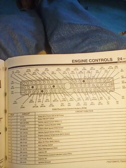
Thanks for the suggestion, where on earth do I find a engine wiring diagram? There must be 100 pins on that connector.


You continuity test of all coil and cps wires, once you have established continuity then also check for shorts to ground
It is VERY likely something wrong with your wiring harness
If it was my truck/engine I would remove the entire engine harness (upper intake too) and inspect it
Removing the harness is easier then you may think!!


Did you install the correct coil pack, for your vehicle?
Does your new coil pack have the firing order marked on the top of the coil pack?
There are two ford coil pack available for the 4.0. The differences are the connector position. One is horizonal and one is vertical and the next is the firing order, which position one and position three, Are reverse.

The information for the correct part is listed below:
Coil pack infor
Resistance in Ohms:
Primary 200 Scale .3 - .9
Secondary 200 Scale 11.0k - 17.0k
There is a ground wire on the coil mounting bolt, which the bolt secures too the coil mounting base. Also the bottom of the coil pack has a ground ring on it , which ground too the the mounting plate.

View attachment 439488 View attachment 439489 View attachment 439490
Thanks for the diagram, a tremendous help. What book do you find these diagrams. I was trying to install a new radio when I found the amplifier is in front of the passenger side rear wheel well. Surprise, suprise.


Thanks for the suggestion, where on earth do I find a engine wiring diagram? There must be 100 pins on that connector.
There is only 60 pins. Its standard on ford models.
There is a ignition coil module, see picture for locatio.
the coil Wires go to the ignition control module, ( which tell the coil to fire).
Then the wires go from the module too the PCM. See pictures.


There is only 60 pins. Its standard on ford models.
There is a ignition coil module, see picture for locatio.
the coil Wires go to the ignition control module, ( which tell the coil to fire).
Then the wires go from the module too the PCM. See pictures.
A word of caution , only use a small needle(pin), when you probe the pins, so not enlarge them.
Ignition module ,you want pins 10,11 and 12. Also pins 8&9
IMG_20230302_135814.jpg IMG_20230302_135843.jpg IMG_20230302_140650.jpg


Back
Top