2000StreetRod
Moderator Emeritus
- Joined
- May 26, 2009
- Messages
- 10,597
- Reaction score
- 334
- City, State
- Greenville, SC
- Year, Model & Trim Level
- 00 Sport FI, 03 Ltd V8
Background
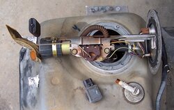
In 1999 Ford switched from a return fuel system with a rail mounted fuel pressure regulator (FPR) to a returnless fuel system with a rail mounted fuel pressure damper and a tank installed FPR. The fuel pressure for the returnless system should be 60 to 65 psi for just about any condition when the ignition switch is in Run. My stock fuel pump was still functional but I needed to install a high flow pump in preparation for adding an M90 supercharger and high flow fuel injectors. In searching the forum I found threads for replacing the fuel pump without removing the fuel tank by cutting a carefully measured access hole in the body panel above the pump. I also found threads about removing the fuel tank and a couple threads about replacing the return fuel system pump. I decided to generate this thread describing removal of the fuel tank, removal of the fuel pump assembly, replacement of the pump, hose and "sock", installation of the pump assembly and installation of the tank on a returnless fuel system.
Note: The Aeromotive Stealth 340 fuel pump I chose to install is not designed for returnless fuel systems and draws about 16 amps at 65 psi. It's 340 liter per hour capacity greatly exceeds the needs of my future M90 equipped engine. According to the manufacturer it can support up to 700 flywheel horsepower on a forced induction fuel injected engine with high flow fuel filter and AN-06 or equivalent fuel line. One reason I selected the pump is it highly compatible with pulse width modulated controllers which I plan to incorporate in the future. I do not recommend this pump for your Explorer nor does Aeromotive.
Fuel tank removal
1. Reduce the fuel in the tank to nearly empty. When my fuel gauge dropped to 1/8 I placed a portable fuel container with 2 gallons of fuel in the vehicle and continued driving until the "CHECK GAGE" illuminated. If your vehicle does not run, or it is not convenient to wait until the tank is nearly empty by driving, then you will have to find some way to empty the tank. If you decide to siphon fuel out of the tank I suggest using the vent port instead of the filler port. The vent port connects to a tube with a 90 degree downward bend in the tank so a hose will go to the bottom of the tank.

The larger diameter filler port connects to a tube with a 45 degree downward bend in the tank. Pushing a siphon hose thru the port results in it contacting the front side of the tank wall. If the pump still works you can pump out the fuel into a container. One way is to disconnect the inlet to the fuel filter and attach a hose to the feed pipe from the tank. While you're doing that consider replacing the fuel filter if it's been 50K miles since it was last replaced. See Why change fuel filter? Don't forget to relieve the fuel pressure prior to disconnecting the feed line to the filter.
2. Relieve the fuel pressure. There are several ways to accomplish this. You can remove the fuel pump relay in the Battery Junction Box (BJB), start the engine and let it run until there is no longer any fuel pressure. You can remove the fuel pump Fuse 9 in the BJB, start the engine and let it run until there is no longer any fuel pressure. You can activate the Inertial Fuel Shutoff, start the engine and let it run until there is no longer any fuel pressure. You can disconnect the fuel pump electrical connector C311 attached to the inner side of the left frame rail forward of the tank. This connector is not available on 2001 and later models. In my case I just let the vehicle sit overnight allowing the pressure to bleed off thru the check valve in the fuel pump assembly and then relieved what was left (none) by depressing the Schrader valve in the engine compartment.
3. Disconnect the cable from the negative terminal of the battery. I disconnected both the negative and the positive connectors so I could clean them and the battery posts.
4. Block the front wheels to prevent the vehicle from moving forward or aft.
5. Lower the spare and move it away from under the vehicle to improve access and visibility.
6. Loosen the lug nuts on the left rear wheel.
7. Jack up the rear axle and place jack stands under it.

I used 6 ton jack stands under the axle and 2 ton stands under the springs for backup.
8. Remove the left rear wheel.
9. My Sport is 2WD but 4WD models may have a fuel tank shield and skid plate to remove.
10. Loosen the vent hose clamp at the tank and disconnect the hose.
11. Loosen the fuel filler hose clamp at the tank and disconnect the hose.

I covered the ports with aluminum foil to reduce fumes in the garage and keep out dirt.
12. Remove the fuel tank ground strap if any (none on my Sport).
13. My Haynes Repair Manual says to disconnect the fuel pump electrical connector inboard of the driver side frame rail and forward of the fuel tank on 2000 and earlier models. My 2000 Explorer Workshop Manual does not mention the step and I found it was unnecessary.
14. Support the tank with jack(s). I supported the fuel tank with scissor jacks and boards for better control.

15. Completely unscrew the bolt holding the rear tank strap in position. It is located above the driveshaft so I used a U joint attached to the socket and a 12 inch extension.
16. Remove the two bolts attaching the front of the tank to the support bracket.
17. My Haynes manual says to bend the tank strap down and out of the way but I chose to remove it which agrees with my Workshop Manual. I pushed the tank sideways toward the driveshaft far enough to swing the strap rearward and align the flat head on the other end with the slot in the frame rail. Then it just dropped down and was free.
18. Contrary to the above photo, lower the rear of the tank about 1/2 inch and then lower the front of the tank while pushing the tank rearward until the tank clears the mounting bracket. There's an aggravating protrusion on the inboard section of the bracket that must be cleared. This avoids stressing any of the tank connections.
19. Lower the rear (and front) of the tank until you can access the fuel line, electrical connector and vapor hose connector thru the wheel well. Do not lower the tank so much that any hose is supporting the weight of the tank.

20. Disconnect the fuel line.
21. Disconnect the vapor hose connector.
22. Disconnect the electrical connector that may be attached to inboard side of the frame rail.

In 1999 Ford switched from a return fuel system with a rail mounted fuel pressure regulator (FPR) to a returnless fuel system with a rail mounted fuel pressure damper and a tank installed FPR. The fuel pressure for the returnless system should be 60 to 65 psi for just about any condition when the ignition switch is in Run. My stock fuel pump was still functional but I needed to install a high flow pump in preparation for adding an M90 supercharger and high flow fuel injectors. In searching the forum I found threads for replacing the fuel pump without removing the fuel tank by cutting a carefully measured access hole in the body panel above the pump. I also found threads about removing the fuel tank and a couple threads about replacing the return fuel system pump. I decided to generate this thread describing removal of the fuel tank, removal of the fuel pump assembly, replacement of the pump, hose and "sock", installation of the pump assembly and installation of the tank on a returnless fuel system.
Note: The Aeromotive Stealth 340 fuel pump I chose to install is not designed for returnless fuel systems and draws about 16 amps at 65 psi. It's 340 liter per hour capacity greatly exceeds the needs of my future M90 equipped engine. According to the manufacturer it can support up to 700 flywheel horsepower on a forced induction fuel injected engine with high flow fuel filter and AN-06 or equivalent fuel line. One reason I selected the pump is it highly compatible with pulse width modulated controllers which I plan to incorporate in the future. I do not recommend this pump for your Explorer nor does Aeromotive.
Fuel tank removal
1. Reduce the fuel in the tank to nearly empty. When my fuel gauge dropped to 1/8 I placed a portable fuel container with 2 gallons of fuel in the vehicle and continued driving until the "CHECK GAGE" illuminated. If your vehicle does not run, or it is not convenient to wait until the tank is nearly empty by driving, then you will have to find some way to empty the tank. If you decide to siphon fuel out of the tank I suggest using the vent port instead of the filler port. The vent port connects to a tube with a 90 degree downward bend in the tank so a hose will go to the bottom of the tank.
The larger diameter filler port connects to a tube with a 45 degree downward bend in the tank. Pushing a siphon hose thru the port results in it contacting the front side of the tank wall. If the pump still works you can pump out the fuel into a container. One way is to disconnect the inlet to the fuel filter and attach a hose to the feed pipe from the tank. While you're doing that consider replacing the fuel filter if it's been 50K miles since it was last replaced. See Why change fuel filter? Don't forget to relieve the fuel pressure prior to disconnecting the feed line to the filter.
2. Relieve the fuel pressure. There are several ways to accomplish this. You can remove the fuel pump relay in the Battery Junction Box (BJB), start the engine and let it run until there is no longer any fuel pressure. You can remove the fuel pump Fuse 9 in the BJB, start the engine and let it run until there is no longer any fuel pressure. You can activate the Inertial Fuel Shutoff, start the engine and let it run until there is no longer any fuel pressure. You can disconnect the fuel pump electrical connector C311 attached to the inner side of the left frame rail forward of the tank. This connector is not available on 2001 and later models. In my case I just let the vehicle sit overnight allowing the pressure to bleed off thru the check valve in the fuel pump assembly and then relieved what was left (none) by depressing the Schrader valve in the engine compartment.
3. Disconnect the cable from the negative terminal of the battery. I disconnected both the negative and the positive connectors so I could clean them and the battery posts.
4. Block the front wheels to prevent the vehicle from moving forward or aft.
5. Lower the spare and move it away from under the vehicle to improve access and visibility.
6. Loosen the lug nuts on the left rear wheel.
7. Jack up the rear axle and place jack stands under it.
I used 6 ton jack stands under the axle and 2 ton stands under the springs for backup.
8. Remove the left rear wheel.
9. My Sport is 2WD but 4WD models may have a fuel tank shield and skid plate to remove.
10. Loosen the vent hose clamp at the tank and disconnect the hose.
11. Loosen the fuel filler hose clamp at the tank and disconnect the hose.
I covered the ports with aluminum foil to reduce fumes in the garage and keep out dirt.
12. Remove the fuel tank ground strap if any (none on my Sport).
13. My Haynes Repair Manual says to disconnect the fuel pump electrical connector inboard of the driver side frame rail and forward of the fuel tank on 2000 and earlier models. My 2000 Explorer Workshop Manual does not mention the step and I found it was unnecessary.
14. Support the tank with jack(s). I supported the fuel tank with scissor jacks and boards for better control.
15. Completely unscrew the bolt holding the rear tank strap in position. It is located above the driveshaft so I used a U joint attached to the socket and a 12 inch extension.
16. Remove the two bolts attaching the front of the tank to the support bracket.
17. My Haynes manual says to bend the tank strap down and out of the way but I chose to remove it which agrees with my Workshop Manual. I pushed the tank sideways toward the driveshaft far enough to swing the strap rearward and align the flat head on the other end with the slot in the frame rail. Then it just dropped down and was free.
18. Contrary to the above photo, lower the rear of the tank about 1/2 inch and then lower the front of the tank while pushing the tank rearward until the tank clears the mounting bracket. There's an aggravating protrusion on the inboard section of the bracket that must be cleared. This avoids stressing any of the tank connections.
19. Lower the rear (and front) of the tank until you can access the fuel line, electrical connector and vapor hose connector thru the wheel well. Do not lower the tank so much that any hose is supporting the weight of the tank.
20. Disconnect the fuel line.
21. Disconnect the vapor hose connector.
22. Disconnect the electrical connector that may be attached to inboard side of the frame rail.