it's not hard to install. there's thread here with pics somewhere. if you have the Mach radio with 6-disc cd player
it will not work. I know, I've tried and even contacted Dorman tech support.
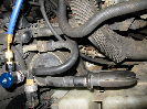
basically, remove the radio. remove the top of the radio. the power board is on the top left side. there's a single screw that comes into the board from the rear of the radio and 2 (3 but you can really only get to 2) metal lugs you have to straighten to release the board and a single electrical plug. this board is to fix the blank display problem only.
Tip: do not remove the front of the radio. it's not necessary and it's a bugger to put back on.
here's the link to the thread w/pics. start with post#17.
http://www.explorerforum.com/forums/showthread.php?t=395093&highlight=586-001