-
Performance Upgrades - Maintenance - Modifications - Problem Solving - Off-Road - Street Trucks.
Covering the Explorer, ST, Sport, Lincoln Aviator, Sport Trac,
Mercury Mountaineer, Mazda Navajo, Ford Ranger, Mazda Pickups, and the Aerostar.
Featuring H.I. - Human Intelligence.
Register Today It's free!
- Forums
- Generation Specific Forums
- 1995 - 2001 Explorer Ranger Merc. 2nd Generation
- Stock 1995 - 2001 Explorers
You are using an out of date browser. It may not display this or other websites correctly.
You should upgrade or use an alternative browser.
You should upgrade or use an alternative browser.
Can CMP Synch be changed with engine in place (4.0 OHV)?
- Thread starter troverman
- Start date
Elite Explorer members see no advertisements, no banner ads, no double underlined links,.
Add an avatar, upload photo attachments, and more!.
4X4 Explorer
Member
- Joined
- February 4, 2011
- Messages
- 17
- Reaction score
- 0
- City, State
- Seattle
- Year, Model & Trim Level
- '96 XLT
CMP install 4.0 EFI
1996 Ford Explorer 4.0 MFI Camshaft Position Sensor (installation)
For those who have the less powerful 4.0…..this is the 160 hp type X engine,,,,,,the changing of the CPM…or camshaft position sensor,,,,,,can be quite a challenge.
This not the 4.0 OHV engine.
I spent hours searching the web for the location of this electrical component. Never did find a good and thorough description. So having finally located and replaced it, I will tell you its exact location.
General spot…….dead center of the engine….all the way back between intake manifold and firewall. Now specifically….inline with the left corner of intake manifold about four inches below the corner bolt. To actually put your hand (if you have small hands) on it you must first wrestle a thick wire bundle and three plug wires. Yes it is directly below these wires. It is tucked behind so snugly that you will probably never see it, This is a feel by hand type of operation. When you feel the flat top with a ¼” bolt on either side slide your fingers toward the firewall. You will now feel, and if properly lighted, see the wire connection.
The most comfortable position is putting down a blanket over engine then laying on top with your head as far back toward firewall as possible.
Check out Auto Zone…………
For a good picture of what it should look like. It is not the same as the other 4.0 engine,
Notice the top of the CPM is flat with two ¼ inch bolts. It is shaped like a light bulb (two dimensional). You can access with a socket and 6” extension.
Because it was my first time replacing this component, I found it helpful to remove coil box and plug wire holder attached above CPM. This allows for better sight lines and more hand/finger space.
Notice the orientation of the component. The wire connection end faces the firewall but not perpendicular (12 o’clock)…….more like 11:00 o’clock.
The two bolts are “kept” on the CPM so do not try to remove completely……..loosen until they wiggle . Pull straight up. The electrical plug can be disconnected with a simple flat screwdriver. Clip is on top of socket…just pop up slightly and pull toward firewall.
Remember to snap fit on top of shaft and point connection end at 11:00 o’clock.
Hand start bolts. Only requires a few twists with ratchet, Do not over tighten
NOTE: Ignore all info about special tool….setting the timing…TDC…..etc.
That is only if you place to change the entire camshaft synchronization shaft
novidyahere
New Member
- Joined
- January 14, 2013
- Messages
- 5
- Reaction score
- 0
I've read that 1996 Camshaft sensor and synchronizer will fit on a 1995 Explorer, is this truth?
I am having a hard time finding a 1995 sensor as it seem to be the piece as a whole.
Any info is greatly appreciated, this is driving me nuts.
I am having a hard time finding a 1995 sensor as it seem to be the piece as a whole.
Any info is greatly appreciated, this is driving me nuts.
Pete Deering
Explorer Addict
- Joined
- November 13, 2019
- Messages
- 1,003
- Reaction score
- 436
- City, State
- New England
- Year, Model & Trim Level
- 1995 xlt 4 door 4x4
Today’s Date 12-11-2019
1993 to 1995 ford explorer xlt 4 door Code X (Cam Position Sensor) Cam Synchronizer Replacement.
On My 1995 ford Explorer 4.0L V6 OVH pushrod engine;I used Cardone A1 84-S2605New Synchronizer.
Tools
1. Rockauto Cardone 84-S2605 (Ford Part # 12K073)
2. Ebay: CID Testing Wiring Harness T94T-50-B (Rotunda) From Ford service manual
And Sensor adjusting Wrench T94T-12270-A (10mm 12 point& 3/8 female drive otherside).
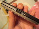
3. I ALSO USED A Borescope (Camera) Ebay: Gintai Smartphone USB wire endoscope($13.00), I brought a 15 Foot scope length, but all you need is 6 Feet. Note Before you purchase any device, first see if you can install the app on your phone from your app store (free).
4. Harbor Freight Magnetic Slim Bar Folding Rechargeable LED Light
5. 19 mm deep socket with a long handle Ratchet
6. 10 mm socket with (2) 3 inch extension & 1.5 inch extension
7. T27 socket used to remove the coil pack 4 screws
8. (2) 11 inch long 1/2 inch drive extension put together
9. Also read Tom Graham Burns, Tennessee November 28,2018 Forum Post
10. I used Duct Tape and masking tape, White Paint marker, and yellow marker
11. I also used Homedepot: General Digital Caliper (Part# 147)
12. X-ACTO KNIFE and a used white envelope
Note NO alignment tool is required. The window has the mark or marks on it. The Synchro is located approximately 3 inch to the right of the trans drip stick. The head of the Synchro is even with the top of the lower manifold. I don’t believe you can see the vane thru window on the top of the synchro even with the upper manifold removed. You can see from the pictures the borescope facilitated the removal.
First I only Removed the coil pack to replace the Cam Synchronizer
I used masking tape to label the plug wire on the coil and record it on a piece of paper for re-installation.
Unplug the coil and removed it
I also removed the pass side inner fender well liner and pass front tire.
I also remove the number one spark plug. I label the plug wire with masking tape.
Remove the Trans fluid drip stick tape up hole
I rotated the crank around with the 19mm socket Looking up at the crank I try to find the 0 degree mark on the crank pulley. I had it at the 6 O’clock. (my pulley had two marks 10 degree ATDC and 0 degrees)
I then used my Caliper on the white envelope and set my caliper to 34 mm (that’s the 26 degree mark you want to be at) and marked the envelope. I used the X-acto knife to cut envelope to 34 mm. I then cut the 34 mm long piece to 1/8 wide.
I the used clear packing tape and tape to the cut piece of paper, to able me to pickup the strip of paper and tape it to the crank pulley.
I set one end to the envelope on the 0 degree mark and press white envelope strip on the pulley, which is at the 26 degree (34 mm from 0 degree. The clear packing tape is holding it in place; I then marked the pulley at the 26 degree mark with the white marker. I then used the yellow marker and highlighted the distance between 0 degrees and 26 degrees. I then rotated the 26 degree toward the pointer. The 19mm and ratchet remained in place. Picture 1
From the pass side wheel well; I marked the engine timing mark pointer with the white marker.
I then rotated the crank pulley around to the timing pointer. I stop short before the mark. I stuck a thin distributor screwdriver into the #1 spark plug hole to see where the piston was. I put masking tape on the screwdriver shaft at the edge on the head. I then continue to rotate the crank to where the 26 degree mark line up with the pointer tip and I then checked the screwdriver masking tape to see if it pushed out more; which it did. the engine was at TDC, if it did not I would have been 180 degree out. If it was 180 degree out, I would have to rotated the crank around (one revolution). Picture 2
I used the borescope to look down at the Synchro (Cam Synchronizer) window. Picture 3.
The picture shows the orientation of the vane to the alignment mark on the window. One thing I did not do is, measure the voltage at this point with the CID Testing Wiring Harness T94T-50-B (Rotunda) Tool.
I should have done this.
I duct tape the borescope to the upper manifold to keep it from moving. Picture 4
I duct tape the vacuum line up and at of the way and the same thing for the wiring harness.
I cut off the pop rivet on the AC line support to lift the ac line up.
I duct tape a mirror to the fire wall.
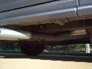
From the wheel well I place the Slim Bar LED Light on the exhaust pipe with bar light at the base of the mirror facing the Synchro. Picture 5.
Note: Put a white mark on the fire wall to show the orientation (direction) of the Synchro connector Body
I disconnected the connector on the CID (Synchro) and tape it out of the way.
I used the Sensor adjusting Wrench T94T-12270-A (10mm 12 point& 3/8 female drive otherside). To break free or loosen the 10mm hold down bolt. I used a breaker bar on top of the wrench to get it to move. It was slow going (If the synchro (connector) was able to rotate to the Left
The problem I ran into was The Synchro was rusted to the Lower Manifold. I sprayed it with penetrating oil and I let it soak for a day or two. NOTE you need to remove the hold down clamp and bolt from the manifold to get the Synchro out.
From the passenger side wheel well
I disconnected the vertical connector on the side of the cylinder head. All need to do stick a long screwdriver in to depress the tab and pull drop. I spray it with silicone spray to help come apart. The top connector, to remove that, stick a screwdriver in at the base of the connector and it will slide up and off.
I remove the white retainer for the Oxygen Sensor and pushed out of place to make room.
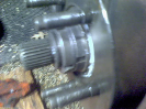
I use the two 1/2 drive extension together and place it against the side of the Synchro and hit it with a ball peen hammer and it move. I was able to spray more lube at the base of the synchro from the wheel well. Picture 6. After a few hits the Synchro moved. The Service manual tells you to rotate the synchro side to side. Which I did. I rotated the Synchro connector to the driver side and note the orientation of the vane inside window Picture 7. The edge of the vane was at the second mark on the window. Picture 8. The original Synchro had two marks on the window. One was a half mark (removal Location, the synchro connector was turned to the driver side), the other a full mark (final location, at original location before removal).
The Synchro would not lift out. I use the two 1/2 drive extension together and place it against the underside of the Synchro and hit it with a ball peen hammer and it pop out. Picture 9 ( I was going to install a socket at the end of 1/2 “ drive extension in the reverse direction or cut a socket wall to give me more surface area on the housing of Synchro, but a couple of hits it more.
After it pop out, you have to have the connector turn to the driver side. I them Lifted the wiring harness running cross the back of the engine, while lifted and angle the synchro out the hole, around the harness and out. Note the vane does not move very easy away from it location when removing it from the engine.
INSTALLATION
You need to check the replacement Synchro to see if it is identical. The replacement Synchro unit only had one mark on the window, so mark the set point on the window, which was the half mark, This is where you set the vane too, when you drop it.( just like a distributor) the connector of the synchro is facing the driver side of the engine open. Picture 10.
Once in the hole the Synchro did not drop into place. I could rotate the Synchro side to side the Vane stay in place and did not change positions. So it was either the Camshaft gear or the oil pump shaft holding the vane in place. I could not get it to drop in; so I ask a friend to help me, I have a piece of plywood across the fender and grill, so you can lie across the top of the engine. Picture 11. My friend push-down on the Synchro while I rotated (a little) the Crankshaft clockwise then Counter- clockwise and it drop –in. After setting the timing back to 26 degree mark. I check the shoulder of the vane in the orientation to the mark on the window. I rotated the synchro side to side to try to line up the mark with the vane shoulder and I was off.
I then removed the Synchro and turn the vane shoulder, where it was inline with the left side of side of window bottom and drop it back in. (the half mark should have been about 3/16 clockwise that window).
It drop right into place. I then adjusted the vane should to the mark on the window Picture 10b and then check the relationship between the white mark I made on the fire wall to the Connector. It was close to the white mark on the firewall. I also checked the Harness Connector for the Synchro to see if it would connect without any stain on the harness and it appear to be OK. I then re-installed the hole down clamp and bolt (10mm). You need to rotate the Synchro Connector to the Pass side direction, so you can get at the bolt with a socket and extension to tighten up. When I got close I re-adjust the vane shoulder back to the mark on the window. I then tighten up the hold down bolt a little more. I then connected the CID Testing Wiring Harness T94T-50-B (Rotunda). The service manual uses this tool. The instruction tells you to connect the positive and negative leads to battery and connect a volt meter to the third wire on the tool. See Picture 12. The Service manual tells you to rotate the CID sensor counterclockwise and stop at the exact point the voltmeter switches from 0 to 12 volts. Which I did. Also read Tom Graham Burns, Tennessee November 28, 2018 Forum Post. Without the tool (T94T-50-B) I don’t how you could do this adjust easily. All the tool is; is a connector with three wires coming off it, one for each of the pins. Positive, negative, center pin is the signal. They want $45 for the connector. It’s $5 at the junk yard; you can cut the harness with the connector on and extend the leads to mark a tool.
I the left the everything in place and tighten down the holding bolt to 13ft-lbs. and put everything back.
Removed the CID Testing Wiring Harness T94T-50-B (Rotunda) tool and Harness connector for the Synchro. Done Picture 13
Picture 1 looking up from under the crankshaft pulley
Picture 2 Looking at the pulley from pass side wheel well. From the side
Picture 3 the bore scope I used
Picture 4 - I Use duct tape to hold everything in place. The bore scope is the black cable tape to upper manifold
Picture 4a Picture from borescope of window on Synchro. This is the replacement with only one mark on the window.
Picture 5 - slim LED light on frame looking at side of engine
Picture 6 Looking from Pass Side wheel well with all the connectors move aside to see Synchro
Picture 7- Factory Synchro Setting at 26 degrees. Vane shoulder in window on full mark. See half mark.
Picture 8- Synchro connector rotate to driver side- for Synchro removal
Picture 9- from pass wheel well – ½” extension 22” long placed under Synchro to get to pop out. It was free moving side to side.
Picture 10a- installation orientation look at vane thru window. No half mark on window so I used a black Sharpe to mark the body
Picture 10b- Final vane location after the synchro is fully seated.
Picture 11- plywood across fender to front grill- this allows me to reach down behind engine to remove synchro.
Picture 12- CID Testing Wiring Harness T94T-50-B (Rotunda) From Ford service manual and
Sensor adjusting Wrench T94T-12270-A


1993 to 1995 ford explorer xlt 4 door Code X (Cam Position Sensor) Cam Synchronizer Replacement.
On My 1995 ford Explorer 4.0L V6 OVH pushrod engine;I used Cardone A1 84-S2605New Synchronizer.
Tools
1. Rockauto Cardone 84-S2605 (Ford Part # 12K073)
2. Ebay: CID Testing Wiring Harness T94T-50-B (Rotunda) From Ford service manual
And Sensor adjusting Wrench T94T-12270-A (10mm 12 point& 3/8 female drive otherside).
3. I ALSO USED A Borescope (Camera) Ebay: Gintai Smartphone USB wire endoscope($13.00), I brought a 15 Foot scope length, but all you need is 6 Feet. Note Before you purchase any device, first see if you can install the app on your phone from your app store (free).
4. Harbor Freight Magnetic Slim Bar Folding Rechargeable LED Light
5. 19 mm deep socket with a long handle Ratchet
6. 10 mm socket with (2) 3 inch extension & 1.5 inch extension
7. T27 socket used to remove the coil pack 4 screws
8. (2) 11 inch long 1/2 inch drive extension put together
9. Also read Tom Graham Burns, Tennessee November 28,2018 Forum Post
10. I used Duct Tape and masking tape, White Paint marker, and yellow marker
11. I also used Homedepot: General Digital Caliper (Part# 147)
12. X-ACTO KNIFE and a used white envelope
Note NO alignment tool is required. The window has the mark or marks on it. The Synchro is located approximately 3 inch to the right of the trans drip stick. The head of the Synchro is even with the top of the lower manifold. I don’t believe you can see the vane thru window on the top of the synchro even with the upper manifold removed. You can see from the pictures the borescope facilitated the removal.
First I only Removed the coil pack to replace the Cam Synchronizer
I used masking tape to label the plug wire on the coil and record it on a piece of paper for re-installation.
Unplug the coil and removed it
I also removed the pass side inner fender well liner and pass front tire.
I also remove the number one spark plug. I label the plug wire with masking tape.
Remove the Trans fluid drip stick tape up hole
I rotated the crank around with the 19mm socket Looking up at the crank I try to find the 0 degree mark on the crank pulley. I had it at the 6 O’clock. (my pulley had two marks 10 degree ATDC and 0 degrees)
I then used my Caliper on the white envelope and set my caliper to 34 mm (that’s the 26 degree mark you want to be at) and marked the envelope. I used the X-acto knife to cut envelope to 34 mm. I then cut the 34 mm long piece to 1/8 wide.
I the used clear packing tape and tape to the cut piece of paper, to able me to pickup the strip of paper and tape it to the crank pulley.
I set one end to the envelope on the 0 degree mark and press white envelope strip on the pulley, which is at the 26 degree (34 mm from 0 degree. The clear packing tape is holding it in place; I then marked the pulley at the 26 degree mark with the white marker. I then used the yellow marker and highlighted the distance between 0 degrees and 26 degrees. I then rotated the 26 degree toward the pointer. The 19mm and ratchet remained in place. Picture 1
From the pass side wheel well; I marked the engine timing mark pointer with the white marker.
I then rotated the crank pulley around to the timing pointer. I stop short before the mark. I stuck a thin distributor screwdriver into the #1 spark plug hole to see where the piston was. I put masking tape on the screwdriver shaft at the edge on the head. I then continue to rotate the crank to where the 26 degree mark line up with the pointer tip and I then checked the screwdriver masking tape to see if it pushed out more; which it did. the engine was at TDC, if it did not I would have been 180 degree out. If it was 180 degree out, I would have to rotated the crank around (one revolution). Picture 2
I used the borescope to look down at the Synchro (Cam Synchronizer) window. Picture 3.
The picture shows the orientation of the vane to the alignment mark on the window. One thing I did not do is, measure the voltage at this point with the CID Testing Wiring Harness T94T-50-B (Rotunda) Tool.
I should have done this.
I duct tape the borescope to the upper manifold to keep it from moving. Picture 4
I duct tape the vacuum line up and at of the way and the same thing for the wiring harness.
I cut off the pop rivet on the AC line support to lift the ac line up.
I duct tape a mirror to the fire wall.
From the wheel well I place the Slim Bar LED Light on the exhaust pipe with bar light at the base of the mirror facing the Synchro. Picture 5.
Note: Put a white mark on the fire wall to show the orientation (direction) of the Synchro connector Body
I disconnected the connector on the CID (Synchro) and tape it out of the way.
I used the Sensor adjusting Wrench T94T-12270-A (10mm 12 point& 3/8 female drive otherside). To break free or loosen the 10mm hold down bolt. I used a breaker bar on top of the wrench to get it to move. It was slow going (If the synchro (connector) was able to rotate to the Left
The problem I ran into was The Synchro was rusted to the Lower Manifold. I sprayed it with penetrating oil and I let it soak for a day or two. NOTE you need to remove the hold down clamp and bolt from the manifold to get the Synchro out.
From the passenger side wheel well
I disconnected the vertical connector on the side of the cylinder head. All need to do stick a long screwdriver in to depress the tab and pull drop. I spray it with silicone spray to help come apart. The top connector, to remove that, stick a screwdriver in at the base of the connector and it will slide up and off.
I remove the white retainer for the Oxygen Sensor and pushed out of place to make room.
I use the two 1/2 drive extension together and place it against the side of the Synchro and hit it with a ball peen hammer and it move. I was able to spray more lube at the base of the synchro from the wheel well. Picture 6. After a few hits the Synchro moved. The Service manual tells you to rotate the synchro side to side. Which I did. I rotated the Synchro connector to the driver side and note the orientation of the vane inside window Picture 7. The edge of the vane was at the second mark on the window. Picture 8. The original Synchro had two marks on the window. One was a half mark (removal Location, the synchro connector was turned to the driver side), the other a full mark (final location, at original location before removal).
The Synchro would not lift out. I use the two 1/2 drive extension together and place it against the underside of the Synchro and hit it with a ball peen hammer and it pop out. Picture 9 ( I was going to install a socket at the end of 1/2 “ drive extension in the reverse direction or cut a socket wall to give me more surface area on the housing of Synchro, but a couple of hits it more.
After it pop out, you have to have the connector turn to the driver side. I them Lifted the wiring harness running cross the back of the engine, while lifted and angle the synchro out the hole, around the harness and out. Note the vane does not move very easy away from it location when removing it from the engine.
INSTALLATION
You need to check the replacement Synchro to see if it is identical. The replacement Synchro unit only had one mark on the window, so mark the set point on the window, which was the half mark, This is where you set the vane too, when you drop it.( just like a distributor) the connector of the synchro is facing the driver side of the engine open. Picture 10.
Once in the hole the Synchro did not drop into place. I could rotate the Synchro side to side the Vane stay in place and did not change positions. So it was either the Camshaft gear or the oil pump shaft holding the vane in place. I could not get it to drop in; so I ask a friend to help me, I have a piece of plywood across the fender and grill, so you can lie across the top of the engine. Picture 11. My friend push-down on the Synchro while I rotated (a little) the Crankshaft clockwise then Counter- clockwise and it drop –in. After setting the timing back to 26 degree mark. I check the shoulder of the vane in the orientation to the mark on the window. I rotated the synchro side to side to try to line up the mark with the vane shoulder and I was off.
I then removed the Synchro and turn the vane shoulder, where it was inline with the left side of side of window bottom and drop it back in. (the half mark should have been about 3/16 clockwise that window).
It drop right into place. I then adjusted the vane should to the mark on the window Picture 10b and then check the relationship between the white mark I made on the fire wall to the Connector. It was close to the white mark on the firewall. I also checked the Harness Connector for the Synchro to see if it would connect without any stain on the harness and it appear to be OK. I then re-installed the hole down clamp and bolt (10mm). You need to rotate the Synchro Connector to the Pass side direction, so you can get at the bolt with a socket and extension to tighten up. When I got close I re-adjust the vane shoulder back to the mark on the window. I then tighten up the hold down bolt a little more. I then connected the CID Testing Wiring Harness T94T-50-B (Rotunda). The service manual uses this tool. The instruction tells you to connect the positive and negative leads to battery and connect a volt meter to the third wire on the tool. See Picture 12. The Service manual tells you to rotate the CID sensor counterclockwise and stop at the exact point the voltmeter switches from 0 to 12 volts. Which I did. Also read Tom Graham Burns, Tennessee November 28, 2018 Forum Post. Without the tool (T94T-50-B) I don’t how you could do this adjust easily. All the tool is; is a connector with three wires coming off it, one for each of the pins. Positive, negative, center pin is the signal. They want $45 for the connector. It’s $5 at the junk yard; you can cut the harness with the connector on and extend the leads to mark a tool.
I the left the everything in place and tighten down the holding bolt to 13ft-lbs. and put everything back.
Removed the CID Testing Wiring Harness T94T-50-B (Rotunda) tool and Harness connector for the Synchro. Done Picture 13
Picture 1 looking up from under the crankshaft pulley
Picture 2 Looking at the pulley from pass side wheel well. From the side
Picture 3 the bore scope I used
Picture 4 - I Use duct tape to hold everything in place. The bore scope is the black cable tape to upper manifold
Picture 4a Picture from borescope of window on Synchro. This is the replacement with only one mark on the window.
Picture 5 - slim LED light on frame looking at side of engine
Picture 6 Looking from Pass Side wheel well with all the connectors move aside to see Synchro
Picture 7- Factory Synchro Setting at 26 degrees. Vane shoulder in window on full mark. See half mark.
Picture 8- Synchro connector rotate to driver side- for Synchro removal
Picture 9- from pass wheel well – ½” extension 22” long placed under Synchro to get to pop out. It was free moving side to side.
Picture 10a- installation orientation look at vane thru window. No half mark on window so I used a black Sharpe to mark the body
Picture 10b- Final vane location after the synchro is fully seated.
Picture 11- plywood across fender to front grill- this allows me to reach down behind engine to remove synchro.
Picture 12- CID Testing Wiring Harness T94T-50-B (Rotunda) From Ford service manual and
Sensor adjusting Wrench T94T-12270-A
Pete Deering
Explorer Addict
- Joined
- November 13, 2019
- Messages
- 1,003
- Reaction score
- 436
- City, State
- New England
- Year, Model & Trim Level
- 1995 xlt 4 door 4x4
I posted a procedure to remove the cam position sensor 1993 to 1995 4.0l job x engine. Just the coil have to be removed. Will post again tomorrow.
Pete Deering
Explorer Addict
- Joined
- November 13, 2019
- Messages
- 1,003
- Reaction score
- 436
- City, State
- New England
- Year, Model & Trim Level
- 1995 xlt 4 door 4x4
Posted a new thread today
Featured images


Featured images
Similar Threads
- Replies
- 190
- Views
- 184,031
- Replies
- 2
- Views
- 748
- Replies
- 0
- Views
- 797