2000StreetRod
Moderator Emeritus
- Joined
- May 26, 2009
- Messages
- 10,597
- Reaction score
- 334
- City, State
- Greenville, SC
- Year, Model & Trim Level
- 00 Sport FI, 03 Ltd V8
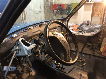
removing PCM loom bracket
The PCM loom bracket protects the wire bundle and prevents it from vibrating.

Unfortunately, it will be in the way of the supercharger intake manifold.

Removing it will give me easy access to the ignition coilpack trigger wire for cylinder pair #1 & #5. First I disconnected the ground terminal from the battery post. Then I removed the bracket mounting nut (11 mm) from the stud in the firewall and disconnected the PCM connector mounting bolt (10 mm).

Then I removed the ground lug mounting stud/bolt (11 mm) and carefully unwrapped the electrical tape that holds the bracket to the wiring bundle.

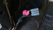
The bracket is shown laying on the upper intake manifold. When I looked thru my wiring diagrams I was disappointed that none of the three paired cylinder trigger wires are identified by cylinder number on the V6 but are identifed on the V8 drawings. When I looked at the SOHC V6 PCM pinout the circuit function was only "Ignition Coil". However, when I looked at the OHV V6 PCM pinout the circuit function of pin 26 was "Ignition Coil #1" and it was the same PCM pin number and circuit function as the V8. The V8 wiring diagram shows pin 26 as being the trigger for paired cylinders #1 & #6 so I assume pin 26 is the trigger for paired cylinders #1 & #5. It's associated wire is tan with a white stripe. I confirmed with a light that there is a TN/WH wire going to the coilpack connector so I found it in the PCM wiring bundle and tagged it with a small cable tie. Then I connected the ground lug to the firewall with the stud/bolt and the PCM connector to the PCM.

And finally I reconnected the ground terminal to the battery post. I think I'm now ready to return to the dyno to get some good pulls.
The PCM loom bracket protects the wire bundle and prevents it from vibrating.
Unfortunately, it will be in the way of the supercharger intake manifold.
Removing it will give me easy access to the ignition coilpack trigger wire for cylinder pair #1 & #5. First I disconnected the ground terminal from the battery post. Then I removed the bracket mounting nut (11 mm) from the stud in the firewall and disconnected the PCM connector mounting bolt (10 mm).
Then I removed the ground lug mounting stud/bolt (11 mm) and carefully unwrapped the electrical tape that holds the bracket to the wiring bundle.
The bracket is shown laying on the upper intake manifold. When I looked thru my wiring diagrams I was disappointed that none of the three paired cylinder trigger wires are identified by cylinder number on the V6 but are identifed on the V8 drawings. When I looked at the SOHC V6 PCM pinout the circuit function was only "Ignition Coil". However, when I looked at the OHV V6 PCM pinout the circuit function of pin 26 was "Ignition Coil #1" and it was the same PCM pin number and circuit function as the V8. The V8 wiring diagram shows pin 26 as being the trigger for paired cylinders #1 & #6 so I assume pin 26 is the trigger for paired cylinders #1 & #5. It's associated wire is tan with a white stripe. I confirmed with a light that there is a TN/WH wire going to the coilpack connector so I found it in the PCM wiring bundle and tagged it with a small cable tie. Then I connected the ground lug to the firewall with the stud/bolt and the PCM connector to the PCM.
And finally I reconnected the ground terminal to the battery post. I think I'm now ready to return to the dyno to get some good pulls.