Mn Mountaineer V8 SAS | Page 4 | Ford Explorer Forums - Serious Explorations

  • Register Today It's free!

Mn Mountaineer V8 SAS

Then i smoothed and matched the radius end of all four plates on the disc sander.
301.jpg

With them all still clamped together i drilled the pivot bolt hole through all of them.
302.jpg

They fit after just a little cleanup with the grinder on the sides.
303.jpg
304.jpg
305.jpg

Welded them in place.
306.jpg

Then i capped them and boxed them on the bottom and front.
307.jpg

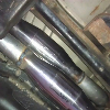
While that was cooling down i cut the radius arms to length.
308.jpg

And tacked the bung's in place.
309.jpg

Still cooling off i put the axle shafts and spindles on the front end, now it's looking more complete.
1
310.jpg

Here is the finished cross member waiting to be cleaned up.
311.jpg
312.jpg
313.jpg
314.jpg


Then i got it in primer.
315.jpg

And paint.
316.jpg


Sunday I loaded parts up and went out to my dad's. I pressed the new wheel studs into the rotors and hubs.
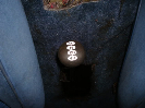
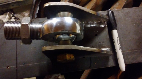
Straightened the cross member in the press, it warped from welding the transmission mount in the center which i new it would. Then i made a tubing swage out of a 3/8" bolt on the lathe to enlarge the inner diameter of the power steering hose. which will then accept the smaller tube i will cut off of the bronco 2 steering hose at the gear end. Then I will silver solder it together.
317.jpg

I helped my dad clean things up at his place for the impending snow, that took about four hours out of my day. When i got back home I put the hubs on.
318.jpg

Then I completely disassembled, cleaned and greased the lockout's.
Reassembled and installed with new allen cap screws.

Just for fun i set the front tires on to see what it is going to look like and check for clearance issues.
319.jpg

While i was out at my dad's i scrounged up some 2" square tubing to make a new front cross member to replace the one that the rack and pinion were mounted in.
320.jpg


My plan is to also use this as a mounting point for the new front bumper when i get to that.


Join the Elite Explorers for $20 each year.
Elite Explorer members see no advertisements, no banner ads, no double underlined links,.
Add an avatar, upload photo attachments, and more!
.


Well no more days off work and i had to clear snow off the driveway last night when i got home so i only had a few hours to work on it. I pulled the transmission cross member and cut it's mounts off the frame.
321.jpg

When i removed the old mount i discovered that the studs were not centered with the bolts so i had to drill another set of holes in the cross member for the new mount to work. It was not a big deal i had plenty of mount area left for adjustment.
322.jpg

Then i was able to bolt the new cross member in, mount the transmission to it and install the radius arms.
323.jpg
324.jpg
325.jpg
326.jpg

I do have a clearance concern with the head pipe. I have a smaller 1310 yoke and will probably redo the head pipe for more clearance.
327.jpg

A view of the monster radius arms finally installed and i think the length will be right, i still have to decide on tires.;)
328.jpg

I went ahead and cycled the suspension and confirmed 5" of compression at which point the tie rod contacts the pitman arm.
329.jpg

I also confirmed that if i put the drag link end in from the bottom of the pitman arm it could hook or make contact with the tie rod. I think i am going to put it in from the top instead to eliminate this problem.
330.jpg

At the current ride height setting it has 6 degrees of camber which is just in spec. If i lower the ride height i may need to swap in 4 degree bushings to reduce the camber angle, the upside would be a little more clearance on the head pipe. It currently has 7 degree bushings.
Still lot's of decisions.


Last night i reamed the pitman arm so the joint is mounted on the top side. Installed a drive shaft to check clearances. Messed with the ride height and checked tire clearances on the fenders. I will have to trim the front fenders whether i use 33" or 35" tires so I went ahead and ordered 35" mt/r k's last night. My solid diff cover for the rear showed up yesterday and the axle shafts are supposed to arrive Friday.


Well so much for the mt/r k's, they just called and said they are on a national back order. The good news is they have bfg mud terrain km2's and are giving them to me at the same price as the good years.:D


Last night i did a rough toe in adjustment so i could get an accurate measurement for the drag link. I cut and tacked the drag link together, it came in at 16 1/2" of tube and overall joint center to joint center length of 29 1/2".
331.jpg

It spun right onto the drag link ends and i eyeballed the tires to center.
332.jpg
333.jpg

Then i took that 29 1/2" dimension and tacked up a track bar.
334.jpg

I jacked the axle up to full bump and set the track bar in to see if i can find a spot that it will clear through the suspension cycle.
335.jpg

It's a tight fit between the pan, diff. cover and sector shaft. I am going to look at putting a bend in it to get more room between the sector shaft and diff. cover.
336.jpg


The new rear axles showed up yesterday and they are beautiful.

I decided to put a bend in the track bar to get it to clear the diff cover, sector shaft and oil pan.

Then i made a couple of tab's to mount the track bar to the frame.

Tacked them in place.

I measured , measured and remeasured the pivot point's for the drag link and track bar. It was not as simple as making the drag link and track bar visually parallel, because of the bend in the track bar.

After i located the mounting point for the track bar at the axle end i made this mounting plate.

Tacked it in place.

Confirmed proper fit and that the bar does not contact anything until full compression.

Then i pulled both the drag link and track bar out and finish welded the ends on.

Here is the axle at full compression, there is about 1/2" of clearance with the pitman arm at this point and the track bar is just touching the oil pan.

I started making the double sheer portion of the lower mount.


I put braces in between the the two mounting flanges.

I made the first of three pieces to brace/box the mount to the axle.

341.jpg
342.jpg
343.jpg
344.jpg
345.jpg
346.jpg
347.jpg
348.jpg
349.jpg
350.jpg
351.jpg
352.jpg
353.jpg
354.jpg
355.jpg
356.jpg


Sunday i finished the boxing of the track bar mount. I still need to finish weld it to the cast iron portion of the axle. I will get that after i get everything mocked up and tear it all out for finish welding.

Then i temped the spring buckets in with screws and clamps.

And it is sitting on the springs front and rear.

I liked how the spring sat on the passengers side so i will use it's orientation on both sides for the final layout.

The rear of the spring buckets fell over the shock relief in the frame from the IFS.

So the next step was to make a template for a filler plate.

The fillers.

Burned in.

I made fillers for the top also and then smoothed it out.

Now i have a nice flat surface on both sides. I cut the lower flange off of the spring buckets and clamped them in place. I used a plumb bob to get them centered over the lower pocket and level at ride height.

Put some heavy tack welds on the four corners.


Then i put the brake calipers and hoses on so i could locate the best spot for the shocks.

I made four tabs for the lower mounts of the shocks.

Sized and d-bur'd like all of the bracket's i have been making.
361.jpg
362.jpg
363.jpg
364.jpg
365.jpg
366.jpg
367.jpg
368.jpg
369.jpg
370.jpg
371.jpg
372.jpg
373.jpg
374.jpg
375.jpg
378.jpg
379.jpg
380.jpg


I located the passengers shock and tacked it in place.
381.jpg

I have the suspension at full bump so i can figure out the bump stop's and upper shock mounts.
382.jpg

I am thinking about doing a tube down the middle of the coil spring with the snubber on the end for the stop. My only concern is mounting the upper spring clamp because the tube will take the center hole for the strap.
383.jpg

I think the easiest and strongest way to mount the shock will be a hoop from the top of the spring pocket back and down to the top of the frame behind the shock.
Oh and the trucking company just called to confirm i will be available to receive the tires tomorrow afternoon. :D:D

In my search for a speedometer correction module i found one from Dakota Digital that i think will allow me to remove the ABS computer as well. This year Mountaineer uses the ABS computer to generate the speed signal (VSS) for the speedometer and cruise control. So if it works i will be able to ditch the ABS computer and pump under the hood which i am not using any ways. As a bonus the module is half the price of ford specific modules.


Tonight i made the bump stop mounts and enlarged the hole in the top of the spring buckets to allow the bump stop tubes to slide into them.
391.jpg
392.jpg

I set them so that the bumpers could compress and hopefully not have the track bar hit the oil pan. Here i have all of the weight on the axle and bump stops.
393.jpg
394.jpg

The next step is upper mounts for the shocks.
395.jpg


The tires showed up today. After work i took them and the old tires out to my dads and used the tire machine to get the new tires mounted up.
401.jpg

I couldn't control myself i tossed a pair on the front axle.
402.jpg
403.jpg

I am so excited these really bring the project to reality.
404.jpg

I will definitely need to trim the rear of the fender, i will start with the front edge of the running boards. Here i have the axle on the bumps.
405.jpg

I was happy to find that the insides of the tires don't appear to rub on the radius arms at steering lock.


Time to get rocking on this. I put the front springs in and put the front tires on again. Then i took it off the jack stands up front.

It sat at what i had decided was going to be the final ride height.

After that i got to swapping the rear axle shafts out. I started with installing the new studs.

Then i pulled the old shafts out, one clip came right out, the other fought for a good five minutes.

The new shafts basically went right back in, very little fuss.

Cleaned up the case flange and put the new Solid diff. cover on.

I forgot to take a pic of that. :scratch:
On went the back tires too and off the stands all the way around.

I am so digging the look of the beast. I can't wait to drive it again.

It is sitting 9"s higher in the rear and 8"s in the front but is still a little low in the rear according to the level. I need to remove the receiver hitch and make some longer shackles for the rear springs. The stock ones hit the hitch and also the frame. If it is still sagging to the rear when i am done with that i will throw the overload leafs back in.
The front coils seem to sit pretty straight at ride height.

They look like they would be happier with a narrower frame but they don't rub the pockets so i think they will be fine.

Overall i am very happy with how it's coming together and am comfortable with moving forward with the mods to the rear and getting the shocks mounted all around.
411.jpg
412.jpg
413.jpg
414.jpg
415.jpg
416.jpg
417.jpg
418.jpg
419.jpg
420.jpg
421.jpg
422.jpg


My speedometer correction module showed up today. I will do a right up on that when i get it installed and this on the road.
I started on the front shock mounts tonight. I was going to do a hoop off of the bump stop tubes sticking out of the spring pockets down to the frame. After looking it over i decided to use 2" square tubing attached to the top and outside of the frame.
431.jpg

The bump's are compressed by the weight of the truck but i know they will compress more under impact so i am giving the shocks about 3/4" more travel than where the bumps are at now. I was able to get the shocks 90 degrees to the axle and front to back. There should be no loss of control from leverage being applied to the shocks.
432.jpg

I measured where the shock was compared to the upper mount tubing and made up this template for the shock tabs. I will also be capping across the tube and upper portion of the tabs for strength.
433.jpg


Sunday i finished the boxing of the track bar mount. I still need to finish weld it to the cast iron portion of the axle. I will get that after i get everything mocked up and tear it all out for finish welding.
IMG_2385_zps752fd9ae.jpg

I like how you double sheared and boxed in the track bar axle mount. I have been looking at mine for about a year now trying to figure out how to turn it into a double shear mount. I was trying to figure out how to clear the steering with a double shear mount. Looks like all you added onto the front where the tie rod passes in front of the mount was about 1/4" width of bar stock. Excellent.


I like how you double sheared and boxed in the track bar axle mount. I have been looking at mine for about a year now trying to figure out how to turn it into a double shear mount. I was trying to figure out how to clear the steering with a double shear mount. Looks like all you added onto the front where the tie rod passes in front of the mount was about 1/4" width of bar stock. Excellent.

Thanks!
Yah i knew from my previous suspension build's that the track bar had a lot of force applied to it all the time, so i wanted double shear at that point. I started with the rear plate to locate the mounting point and built off of that. This was one of those areas that i did not have any advance plan and just looked at it from several angles and then just went at it. The forward most piece that is bent back into the cast end is a 2" wide piece of 1/4" bar stock that i just kept bending a little at a time until it just touched the knuckle. Then i boxed it off of that to the axle tube and rear mounting tab. It is rock solid now, i tend to over build things. After it was done i started looking at it and i think i will be able to mount the future steering ram off of that same mount with no concerns about strength.

I have been following your thread and like how you made the round tubing work in the old square tube you had for the rear cross member. That came out really nice. I'm anxious to hear how the changes effect how yours drives. I still have to tackle the rear shocks on mine.


Thanks, I do like the new rear shock setup. It shouldn't effect flex, but should take away my body roll issues.

Another good thing about double shear is you don't have to worry about the nut working loose like with a single shear. I spent about an hour drilling through the grade 8 bolt to put in a cotter pin.
Keep up the good work.


Thanks. The shocks should work much better now for my rear suspension.

Another good thing about double shearing the track bar mount is you don't have to worry about the nut turning loose. I spent over an hour drilling through the grade 8 bolt and nut to get a cotter pin in there. I went with a Duff lift bracket for my axle mount, which in their defense they were not sure would work on a F-150 axle. Its 3/8" plate with a 1/4" ring welded at the bolt mount hole. I had to modify it quite a bit to get it to line up, then I gusseted the heck out of it. Its very sturdy as is, but now I can double shear the mount. Here is a pic of what I did. Pay no attention to the frame track bar as its completely different now (much lower).
IMG_20131204_115301_540_Large_.jpg


I hear you on trying to machine or drill grade 8 hardware. That Duff mount does look very substantial and single shear is how ford built them to start with but double shear is just that much more strength and piece of mind. It looks like you should be able to do yours similar to mine no problem.


Last night before i tore back into the front shock mounts i clean up the tailings from the iron worker shear area. I am still amazed at how fast i can make brackets with this, so should have had one years ago.
441.jpg

I cut the second tube and made the tabs for the front mounts.
442.jpg

Lined them up with a small washer in place to allow for the tabs pulling together.
443.jpg

And burned them on.
444.jpg

I made caps for the top of the tubing. I was going to wrap the cap over the top of the tabs too but then after looking at it why. The tabs are 1/4" plate and the tube is 1/4" wall with a 1/2" grade 8 bolt holding them together through the shock. If they bend it will be the least of my worries.
445.jpg

Finished shock mount ready to be welded to the frame.
446.jpg

Then tacked in place.
447.jpg

Drivers side also. Notice i still have about 3/4" of shock travel available and the bump stop is compressed. so i am not using the shocks to stop the suspension travel.
448.jpg

I dropped the front axle past where the springs can be inserted to check the shock travel.
449.jpg

The shock may have traveled 7 inches, they have 10 inches of travel total.
450.jpg

I put the springs back in and it now has about 3 inches of compression up front with where the bumps are at which should be fine.
451.jpg

452.jpg

I knew the old shocks were getting a little week before i took this apart but i think it has better shock control now with just the front shocks in and set on the softest setting. The suspension moves but i can hardly get any roll out of it pushing down on any of the corners. Maybe i won't need a front sway bar.
453.jpg


I pulled the receiver hitch off yesterday.
461.jpg

I knew it was bent but found it was cracked also.
462.jpg

With it removed i discovered that the shackles were not actually hitting the frame just the hitch mounts. Even after i flexed the rear some. So for now i will leave the shackles alone, new ones someday though.
463.jpg

The flex seams to be pretty even front and rear.
464.jpg

After that i pulled the rear tires and let the suspension do a full droop to size up the shock mounting locations. With it at full droop the drive shaft pulls quite a ways out of the t-case.
465.jpg

So i picked up this spacer to help.
466.jpg

I put that in and moved on to the rear shock mounts. I decided to use the front edge of the original cross member for a starting point. This point is a little outboard of the original shock location.
467.jpg

Here is the orientation i came up with.
467.jpg

468.jpg

I had to put two 1/4" spacers against the cross member for the shock to clear at full compression. I welded them to the cross member and then added a long tab from the center of the cross member to put it in double shear.
470.jpg

Then i busted out the CAD (cardboard aided design) to make the lower tabs.
471.jpg

The outer tab needed to be a little shorter than the inner.
472.jpg

Welded and painted.
473.jpg


469.jpg


Join the Elite Explorers for $20 each year.
Elite Explorer members see no advertisements, no banner ads, no double underlined links,.
Add an avatar, upload photo attachments, and more!
.


Great work so far man. By chance do you have a build thread for your '83 ranger with the 351w, C6 and np205 ? I'm doing a '89 F-250 351w, C6 and 1356 swap into my '03 Sport Trac that I'm also SAS'ing and will be running 37's.


Back
Top