How to: - 5R55E Rebuild DIY Diary | Page 2 | Ford Explorer Forums - Serious Explorations

  • Register Today It's free!

How to: 5R55E Rebuild DIY Diary

Input Sprag

JK, is this the part you are referring to? (I'm obviously a noob w/ transmissions)

GBvapPzYeqFiG5-3EuDF-YNCbI2EJQO-s5iVnH5Ykyo=w888-h660-no


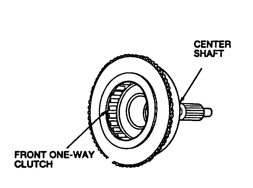
What do you usually see in terms of damage to the input sprag? Assuming I have the right part, ATSG manual says to inspect for:
- cracks on the roller cage
- wear on the roller clutch
- the press fit of the clutch to the center shaft
- excessive wear or damage to rollers and springs
- bent or damaged spring retainers within the roller cage

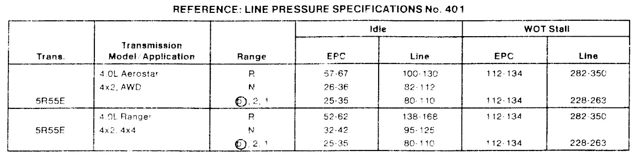
I've been going through the ATSG manual, and it is pretty thorough without being overwhelming. I'll perform the line pressure test again before i start the removal process, just to see if there's a difference, though I doubt there will be.

I did notice that the manual only seems to diagnose the WOT portion of the test by stall speed (spec is 2400-2800) rather than pressure - although I suppose the two are inversely related.

JNrdXjXdR5bDOOlnPlsadyeXNROeIKQz45oKxsJE41U=w1280-h383-no


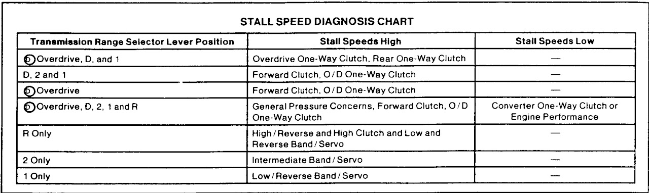
A high stall speed in D and/or OD indicates a failed forward clutch, and/or O/D one-way clutch (sprag). Note that although I do not have reverse engagement, the line pressure test at WOT in reverse was close to spec (probably user error). Here is the chart:

zCevMx5oO49D0JQjKPFCJ8Y6CR4WpnUIV5jrXUC8fHA=w1280-h314-no


I'm feeling much more confident about a rebuild now that I have gone through the manual a bit - in addition to Glacier's A4 build. My next concern is limiting the expense for tools to do this job.


Join the Elite Explorers for $20 each year.
Elite Explorer members see no advertisements, no banner ads, no double underlined links,.
Add an avatar, upload photo attachments, and more!
.


This is a broken input sprag, they can fail in many different ways, this one failed by the little cam teeth flipped over. This one created no debris in the pan, but sometimes they just explode into a mess.


2012-11-05_17-16-57_181.jpg


I wouldn't put to much thought into the pressure or stall readings at this time, without the tranny being able to hold in reverse and drive your WOT readings are going to be low anyways.


Its time to get this thing out and take it apart.


.


Progress Update

I decided to forego the second pressure test. I've got the transmission out now.
For the benefit of others pulling their transmission out, I found this description fairly accurate for the 5R55E as well:
http://www.explorerforum.com/forums/showthread.php?t=126647&highlight=transmission+removal
I would make the following suggestions/additions for the 5R with 4WD (i.e. t-case too):
  • the VSS is located on the t-case
  • remove the transfer case shift motor and hall sensors - the brown wire must be cut and and later spliced on install if your haven't already removed your t-case - this includes the main t-case wire harness of course; remove vent tube as well
  • i could not for the life of me get both hands on the upper wiring harness connectors for complete removal in behind the cylinder heads, so i routed the harness out of the way over the drivers frame rail instead, tucking the wire beside a rib in the steel flooring above the trans - this worked fine
  • use of the floor hatch is essential, getting the upper mounting bolts would have been almost impossible without, plus it makes a few other parts easier like removing the heat shield nut, disconnecting the rear O2 sensors (same harness as transmissison), strapping the transmission jack
  • remove the crossover pipe - consists of center section of driver's exhaust including drivers cat - other side is not necessary
  • if you decide to take the transmission and t-case out together like i did, a transmission jack is essential - i picked up a used harbor freight one on craigslist - the balance point is right about the tailhousing to the rear of the pan, but that's where the crossmember is, if i were to remove again i would hold up the rear and slide the jack back after removing the crossmember
  • i was using jackstands, not ramps or a lift, so i still had to work the trans off the jack under the car in order to slide out on some old carpet and clear the running board - removal of the trans vent pipe at this stage gives a bit more clearance - i used the stacked block method to do this from a safer height
  • the screwball angle of the nut mounting the fill tube to the the cylinder head required removal of the airbox, in order to slide over the coolant/windshield fluid reservoir
  • there is a bracket bolt for the trans cooler lines that can be accessed through the passenger wheel well to free up some movement in the hard lines
  • there are 4 different types of trans to block bolts (8 total), so pay attention during removal, a mechanics magnet is also very helpful for pulling out the upper bolts, wobble joints and u joints required as well
  • before tilting down the tail of the trans, don't forget to remove the fan shroud bolts and free up the shroud (doesn't have to be removed), this prevents damage to the fan shaft as the engine tilts back
  • after tilting down the tail of the trans an inch or so don't forget to support the engine at the aft of the oil pan with a block and jack - the bottle jack works well here - otherwise potential damage to the intake manifold and various wiring harnesses could occur as the engine ****s back towards the firewall
  • I'm guessing the combined unit weighs 200-250 lbs

I'll be on vacation for a few weeks, then I'll get to the teardown!
EvdZjQGQyBxRXZQd0_tZTaHhgD6Y898HRE5ZA=w946-h710-no.jpg


On the Money

It looks like JK was on the money - the input sprag appears to be jammed up:
(lost photos)


Comparing the angle of the rollers to JK's pic (as well as the reverse sprag), it looks like the rollers should be relatively upright, and only become angled when obstructing motion in the wrong direction. Somehow it seems there was too much force in the wrong the direction jamming the rollers stuck.

I believe I am supposed to be able to spin the inner clutch in one direction, but I cannot move it at all (although there is no visible damage or scoring). Does it look like I'm on to the problem?

Otherwise, I've got it mostly apart:


As you can see I haven't yet removed the transfer case or tail housing. I'm not sure it's worth doing so either, as I seem to have found the culprit, and all that remains is the output shaft and parking prawl. Thoughts?

Every other part looked to be in excellent condition except for one of the thrust bearings had a couple rollers that fell out - that will certainly need to be replaced.

I have not yet taken apart the drums to inspect the condition of the clutches, though I'm expecting they will be good. I'll have to buy one of those press tools.

Overall the disassembly was straight forward by the book. I mounted the unit on an engine stand at the tail housing mount bolts (w/ a few washers stacked). This was a great idea! I also made a platform and put it on a furniture dolly to layout all the parts and keep them organized and labeled. Then when I was done for the day I could wheel the platform and engine stand out of the way allowing me to still my park my good car in the garage.

The two tricky parts were removing the servos and the snap ring which retains the reverse drum. I used a 90 degree rad hose pick (with tape on the end to blunt it) to pop out the servos (not having the special tool). Snap ring pliers (not needle nose) are a must to get out the snap ring for the reverse drum, and even then it is tough.

I'd also like to get opinions on what parts I should replace for the rebuild given that almost everything looks excellent. I would prefer to spend less money, but am willing to spend some if the reliability seems worth it.

One last thought - the input sprag is the exact same part that failed last time this trans came out (repaired under warranty). Is this a weak point in the 5R? Or does it point to some other part that may be failing?

Thanks everyone for the help so far.


Yes I believe you found the problem for sure, the planet should turn counter clockwise and lock the other way. The sprag is a weak spot but I am not aware of any other component contributing to its failure, the bands fail more often in my opinion, they can just break anytime.

I would look real carefully at the race on the overdrive planet and the race inside the center shaft (where the sprag is installed). There should be no damage to the races, they need to be smooth. You can drive the bad sprag out from the center shaft using a round punch through the holes on the back.

If you are good with the transfer case still attached then leave it, the only thing to worry about is the gasket and maybe the thrust washer behind the parking gear becoming dislodged. If the the output shaft in the case doesn't move around too much then you should be good. If the washer falls out of place you will know it when you go back togther with it and can't get the snap ring that you removed with the snap ring pliers back in the groove.
The guys in our shop remove the transfer case for a easier removal and installation of the tranny and I would remove it so I can wash the case and it makes for easier handling during a rebuild, for me.

As far as what to replace at this point I would obviously replace the sprag and any component that it might have damaged when it failed, both servo pistons and all three bands. Once you get the clutches out of the drums make sure the steel plates are in good shape with no scratches or hot spots, if they are damaged I would get a master overhaul kit with the steels. The kit will give you all the seals, gaskets, sealing rings and clutches needed.

Its up to you if you want to replace the seals in the drums, I do but it's easy with the tools but I can understand not wanting to battle the springs and snap rings without the press but it would be ideal for new seal. If the clutches are not burnt or the drum hasn't been hot I would say the seals are probably ok, I never see problems with these seal unless there is a lot of damage anyways.

Other areas to look for wear or damage is the bearings in the forward planet and the overdrive planet, look for wear on the sun gear shell sometimes the drum beats on the lugs on the shell. Check the spines in the overdrive planet where the input shaft rides, sometimes they strip out. The pump gears can wear, but if you take it apart you will need a alignment tool or take a chance aligning it with the converter (which I have done many times without issue).

Good job on getting this thing out and apart, you will have this thing fixed and back on the road in no time.:thumbsup:


Forward Clutch / Sprag Install

Thanks for the response JK, I'll check the parts you mentioned.

In the meantime, I realized that I could inspect the clutches and steels w/o buying the press tool (although I have found a cheap knockoff of OTC-7024 on ebay for $36 - so I may get that anyway if I decide to buy a rebuild kit). Here is the forward clutch:

(lost photos)

As you can see, the clutches and steels appear to be in very good condition. So I am leaning towards not replacing the drum seals at this point. I'll inspect the other drums in a bit.

Thanks for the advice on driving out the sprag - looks like a ~$30 part online. The manual is not very helpful on this point:


It's basically saying to replace the assembly. What tool would you recommend for pressing the new sprag back in place? I recall the auto parts stores having some bushing/bearing driver set loaners, but I don't think they went quite that large. Obviously that would be a massive socket, which may not be available either. I'm sure there's something simple, it's just not coming to mind.


Input Srag Bent

I took a closer look at the input sprag again, and noticed there is a small portion of the cage which is out of round - basically a flat spot - likely the result of the thing getting jammed up. You can see this if you look closely at the lower portion of the 2nd pic on post 24.

It just kills me that all this work is to fix a lame bearing (it's not really a bearing, but close enough).


You may end up needing the center shaft if the failed sprag has damaged the outer race, so make sure you inspect it and the race on the planet.

I have a tool that helps with the installation of the sprag but you might be able to work it in by hand and once you get the cams all past the edge you could turn it over and use the table to support the sprag and press the center shaft down onto the sprag or keep pressing it in with your thumbs.


Coast Clutch Toast / Race Condition

The coast clutch and front/OD planetary were somewhat stuck together. I managed to coax them apart with my trusty flathead though. I opened up the clutch pack to find this:

(lost photos)

The top steel was warped - that's not from careless removal:


Where are the friction plates you ask? Incinerated... actually you can see the charred remains on one of the steels. I guess things aren't so pristine on the inside after all.

I removed the sprag from the front center shaft (seems like an oxymoron to be front and center but i digress):


Of course it's a weak spot - its plastic! Before removal I verified the failure by inserting the front/OD planetary into the sprag - it spun freely in both directions, no surprise.

Now to the race surfaces on either side of the sprag. First the inner race:


Now the outer race (on the front center shaft assembly):


I would not characterize either race as truly SMOOTH, but both exhibit what I would describe as minor discreet indentions, not scoring. The pictures show faint markings from the sprag rollers - if it makes sense they feel how they look, relatively minor (actually the inner race feels better than the pic looks), but probably not removable with emory cloth or something similar. What do you think JK? Do I need to shell out more dough and replace these hard parts too? I can't tell off-hand if the inner race is separable from the front/OD planetary. If not, I'm sure that will be a pricey part.

The sun gear shell looks good. As does the forward planetary and the front/OD planetary. Sounds like a rebuild kit will be in order at the least. If I go ahead with replacing the seals on the direct clutch pistons, do I need the "sizing tool"? I recall Glacier doing a trick where he installed the piston and put it in the freezer, maybe that would work here.

What are your thoughts on replacing the "one time" use items?
So far manual has called for: bell housing bolts, tourque converter nuts, band adjuster lock nuts, snap ring on output shaft

That's it for now, one or two more drums to inspect. :scratch: and maybe the pump, though I'm inclined to leave that part alone.


I wouldn't use the center shaft or the planet, any dents or damage here could cause the new sprag to fail prematurely. Rarely do I see a failed sprag like that and no damage to the other parts.

You don't need a sizing tool to get the pistons and new seals back into the drum, most of the time you can get them in by just working them with you hands. You may need something like a feeler gauge to work the seal lip in, the kit may give you a round plastic disk to help install the seals.

I have never replaced the pump bolts or bellhousing bolts or converter nuts or that snap ring that is recommended by the manual because of a one time use situation. The band adjustment nuts should come in the kit, if not use a dab of silicone on the them to keep them from leaking.

The clutch friction disks are the ones with the teeth on the inside, the steel plates are ones with the teeth on the outside. Looks like all the friction material is burned off all the clutches in that drum.

The sprag failed because the little cam teeth wore down enough to let them flip over, this caused the dents in the races and broke the outer plastic ring on the sprag when it failed, rather than the plastic ring broke first and caused the failure.


Inner Race

Thanks for the great advice again, as always. I would have much less confidence in this rebuild job without it. It appears the inner race on the OD planetary is not removable/serviceable. Do I have that right?


Unfortunately the race is part of the planetary.


Intermediate Drum / OD Band / Reverse Drum / Input Shaft / Center Shaft

The intermediate drum appears to be in good shape:

(lost photos)

The OD Band appears to be toast:


The reverse drum seems to show hot spots on both sides:


The surfaces feel perfectly smooth. What do you think?

The input shaft is showing a hot spot where the OD planetary would ride:


Again, it feels smooth as well.

I've given a little thought as to the last few posts and replacing the OD planetary (inner race) and the center shaft (outer race). I think I agree that the OD planetary should be replaced. But thinking about the function of the center shaft, specifically the outer race which holds the OD sprag, I'm not so sure. Correct me if I go astray here, but it seems that the press fit of the OD sprag means that the outer race does not exhibit frictional force. I guess what I'm thinking is, if the sprag is functioning correctly, do the teeth bite on both the outer and inner race, or just the inner race (with the sprag cage providing counter-force)? If the latter, that would imply that minimal wear on the outer race is not that consequential, allowing me to re-use that part. EDIT: Looking more closely at the sprag cage, it looks like the teeth would in-fact require the outer race for counterforce, meaning I need a new one. Trouble is, I can't find a new one online anywhere. There is a used one on ebay though... What do you think about this logic? I don't mean to question your advice and experience, just want to learn and save money. :D

I like the prices and parts availability on this site:

https://www.americanpowertrainwarehouse.com

The part descriptions (identified by exploded diagram #) are good here:

Trans Parts Online A4LD 4R55 Transmission Parts

So far the list of replacement parts is:
OD planetary - $80
OD sprag - $25
center shaft - can only find used on ebay - $40
Int & OD band - $20 ea., but 1 included in kit
Rev Band - $60 (too expensive to just replace when part appears good - reverse band is much sturdier than the two others)
Int and OD servos - $15-$20 ea. (maybe as preventative)
Coast Clutch frictions, steels, seals - $170 for master kit (could alternatively po' boy just needed parts for ~$100, will probably do kit)
10B thrust bearing - appears to be part 254 on diagram - $17
See the missing rollers? Two of them fell right out upon removal, the third must have been consumed.


Any input as to brand of replacement parts? And/or supplier? I assume it is like most other parts, where there is a range of quality - where I generally go middle of the road. Perhaps the production is low enough though that there is only one or two parts makers. I assume buying "good quality" used parts would be counter-productive, but the thought crossed my mind on the hard parts. I've been to a number of trans parts websites, but they don't seem to list the brand of part maker, and many have only some of the parts I need. The overhaul kits seem to be thin on information as to what they include as well.

Another question in my head is the select fit retaining rings for the drums, according to the manual anyways. This means when I replace the frictions and steels, I will need the proper thickness retaining rings, however I don't see different thicknesses listed on parts sites, just one part #... hmmmm. EDIT: The ATSG manual does list P/N's for the various thickness of retaining rings (apparently Ford P/N's), so I can go that route if need be. Just surprising I wouldn't see the range of ring thickness selections listed on every transmission parts site, this seems like a necessity for any proper rebuild.

Too many noob questions, I know. :scratch:


I think it's important to have smooth races for the sprag, I understand it fits tight into outer race but I wouldn't think it will stay there, it may turn. It's just not worth the risk to save some cash to me, its already a weak spot.

20151019_163148.jpg


The hot spots on the reverse drum are from machining during the manufacturing of the part, so that is normal. Just so you know that low sprag is known to fail as well, something to think about.


The input shaft has a problem, it got a bushing stuck to it, that raised area is not supposed to be there, it's a bushing from the inside of the little sun gear that fits into the planet, You will need to replace the sun gear for sure and the input shaft if you can't remove the bushing and polish out any damage to the shaft.


20151026_134757.jpg


I dont mind using a used part if its in good shape and I have used new remanufactured items like the overdrive planet with good results.
I buy parts from mainly from Transtar, and a few other local outlets the area and haven't used the online stores. You should call them and have them help you get the right parts. Transtec kit is a good kit and it will have everything you need in it.

I doubt you will need a selection of snap rings for the drums, the original ones should be fine. I rarely have the adjust the clutch clearance when building the 5R55E just make sure they send you the correct clutches.


Excellent advice, thanks. That would explain why I had to remove the pump/bell housing before removal of the input shaft. Add another part to the list, more $$$$.

I noticed the reverse sprag was quite a bit more expensive than the OD, about $60-$70 I think. I'll probably leave that one be.


End Play Measurements / Pump Alignment / Helpful Videos

I've started ordering parts now - from various sources. I've re-read Glacier's rebuild of the A4, specifically the parts where he measures end play for both the back and front sections of the case. I plan to use a home-made bar as Glacier did ($50 for the real deal, no thanks). But I noticed that measuring the front end play requires disassembly of the pump from the bellhousing. So the question then becomes, why is using the TC to align the pump a "no no" (instead of the alignment tool)? I noticed that you mentioned in an earlier post that you had done so w/o issue. Is there some degree of error that you have to eyeball centeredness of the pump when using the TC instead of the proper alignment tool?

I did find a pretty good video on pump alignment using the TC here:


If the links ever get broken, search Hiram Gutierrez on youtube. He has a bunch of videos.
It looks like there is a little play in the alignment when he does it, but I think I'll go ahead and disassemble the pump so that I can both check the condition of the gears, but also check the end play when reassembled.

The same tech also has a pretty darn good teardown video of a 4r44e - and he even explains the differences to the 5r55e:


I wish I had come across this a while ago! At about 14:30 into the video he describes my exact symptoms as being caused by the OD sprag. Man is he fast, wonder how many times he's done that one... :D

He also recommends replacing the Turbine Shaft Speed sensor (TSS), as a common failure point, but notes that servo bore wear is more common on the W, N, and S, models, not so much the E. Also a good note on inspecting the lining of the reverse band at the apply points (middle towards the anchors) and checking the depth of the grooves - kind of like tread wear on tires. Another failure point is the needle bearing that rides b/w the rear case hub race (aka inner reverse sprag race) and the output shaft ring gear - another failure point on my unit.

A little more inspection, then I'll place the rest of my parts orders. I'll list out the parts, tools, costs, and websites once I have it all figured out.


I use the tool because I have one, it makes assembling the pump easier than using the converter. I thought the way he did it was weird with putting the converter in first then the plate then the pump with gears and having to hold them with a screwdriver. When I did it I assembled the pump completely and left the bolts loose enough to still move around then put the pump down on the converter and installed the input shaft, lined up the bolt holes and tightened the bolts down while turning the pump. I think the tool does a better job because it holds the pump stator better rather than the pump stator and input shaft floating around in the splined components inside the converter.
If you look into the converter you will two sets of splines, this is what the pump stator and input shaft spline into, these components (converter stator and impeller) can move from side to side. The main object to line up the pump is to have the pump stator in the center of the pump bushing, so if you are using the components inside the converter that can move around it is possible to line it up off center, the tools hold the pump stator shaft to the center of the bushing without the chance of movement.

This is the tool that I have it centers the shaft at the end where the sealing ring goes. The pump bushing in the bellhousing rides on the outside surface of the tool.

20151028_115043.jpg


20151028_115053.jpg


Here is tool found in a shift kit for the 5R55W/S transmissions it will work on these too.

-5r55w-shift-kit.jpg


20151028_115457.jpg


20151028_115506.jpg


If you are following Glaciers build of the A4LD be careful with the pump gasket, he has it on the wrong side of the pump wear plate. The gasket should go on the plate to case not plate to bellhousing.


I have never checked end play the way Glacier did it, I use what is called a H guage and there is no need to disassemble the pump. I dont expect you have one and it would be ideal to check endplay but... I rarely have to adjust the end play on one of these and I bet if you put everything back in the way it is suppose to be you wont need to adjust it either. I would just assemble it back together and if you can turn the input shaft its probably good.


.


Pump Alignment

In this case it seems too much information is causing indecision, assuming I don't want to spend the $90 bucks on a precision piece of pipe. On the one hand, if I don't take the pump apart, I can't check endplay (w/o more $$ tools), so there's a risk there, but I should feel good about the alignment. On the other hand, if I take the pump apart I can inspect the pump gears and check endplay, but I risk misalignment - where apparently there is only one thousandth of inch tolerance - I could destroy the bellhousing bushing, pump, maybe toast entire trans. I've read that most shops don't use the tool, but also that rebuild failure rates are high, especially on front seals. :scratch:

I guess after writing this out, it seems like the bigger risk is pump misalignment rather than improper end play. So I'm leaning towards not disassembling the pump. Why didn't they put freakin alignment pins on the thing? Don't answer that.

Oh the cheap *******'s dilemma...

I've also noticed watching a few trans teardown videos how excited the techs get when they find the smoked clutch pack. Just funny I thought.


Parts List / Cost

Here's the damage (let's forget about the $100 I WASTED trying to fix the trans before removal):

(lost photos)


$250 for a valve body I probably did not need, but I won't call that total waste
$140 in tools - YMMV, I have an okay set to start with, this is pretty much the bare minimum of specialty tools to do this job
$300 in parts and fluid - I opted to poor boy this one and am just replacing the seals on the OD, as well as the damaged parts; the only part I'm replacing that didn't necessarily "need it" is the intermediate band

I know, I know, I can feel everyone shaking their head at me, but this project was just getting too expensive for the value of the vehicle, so I saved $130 versus a master rebuild kit. We shall see in time if this proves to be penny wise and pound foolish.

I was able to get that stuck bushing off the input shaft fairly easily, there was minor scoring, but it polished up fairly well. It's not perfect, but looks good enough.

EDIT: You actually need 10 qts fluid for a full refill, I already have a few, but you can get some cheaper Merc V at wally world for about $4/qt instead of $6.50, which adds up to $25 saved for the fill.


Join the Elite Explorers for $20 each year.
Elite Explorer members see no advertisements, no banner ads, no double underlined links,.
Add an avatar, upload photo attachments, and more!
.


My compressor tool (OTC-7024 knock-off) arrived today! Here it is in action:


(lost photos)


You basically just turn the bolt on the bottom and this presses the "feet" down on the piston (allowing for removal of the snap ring) against the counter force of the bottom plate of the tool. Very easy to use. A good buy for $37.

And here is the OD/Coast Clutch drum fully disassembled:


The piston seals were not cracked or brittle, but the rubber was certainly on the hard side. Replacing these seals was a good call. Another good reason for removing the piston on a failed clutch pack is that it allows you clean out the debris from the toasted friction plates. It was pretty nasty under there. The outside of the drum looks bad, but the surface is smooth. It cleaned up fairly well with some 500 grit (technically this is too coarse, crocus cloth is preferred, but is a bit pricey, and I already had 500, good enough IMO).


Back
Top