How to: - 5R55E Rebuild DIY Diary | Page 4 | Ford Explorer Forums - Serious Explorations

  • Register Today It's free!

How to: 5R55E Rebuild DIY Diary

Disassembly & Carnage Pics

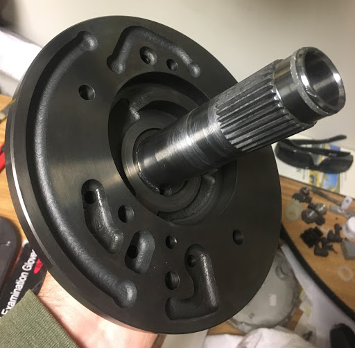
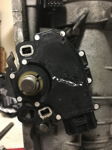
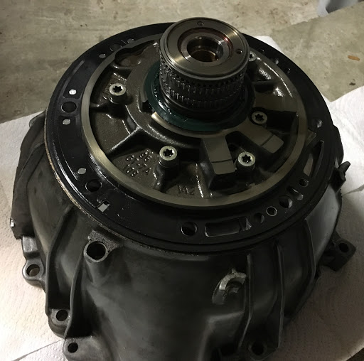
Fist we remove the outer components - here we have the useless ((ODS) overdrive drum speed) sensor (basically a hole plug) for the E model. If you have been following this thread, the last rebuild replaced the OD planetary with a W/N/S version that has an additional reluctor ring. During the install I realized this sensor went unused, but we figured the new OD planetary gear actually would provide an ironically functioning signal.

Rzx8xoT4u9yfeR3s6o8-vqZJ7FNIEYOW_6Zgv47Kqy9nMHsfnVWa5nx2VpZ5D6Un9-pfD2MdftZoVN6JXRfT-sTHv542XcMbbNOTH4zeF-GTNVtF5sVvtZB_QmlZgTrQsN4nBQ


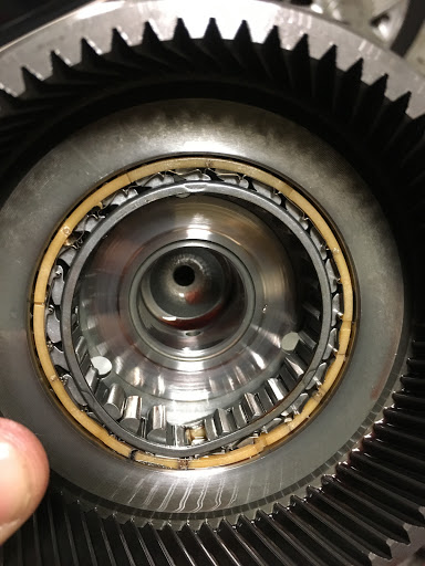
However, when I took a close look this time (below) you will see that the position of the OD planetary reluctor (middle of pic) is much lower than the sensor (tip of screwdriver). The W/N/S must have the OD planetary position higher in the geartrain or possibly an additional reluctor on the OD drum.

pjxUtJ94AP2jBi2cefS0KHOxYM5ehEIJtqdm1lpMnA9yvsqsxoo0TUwrKatu0GbXXnHT6wlHKAHys1kOi67USgJ7_zP0j3jhSOIO6kMo4JRUDhaF0AmmB6Y6l_6eFY-Lwq7gZQ


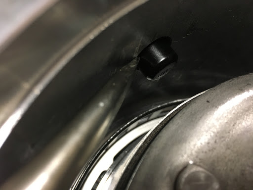
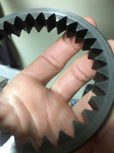
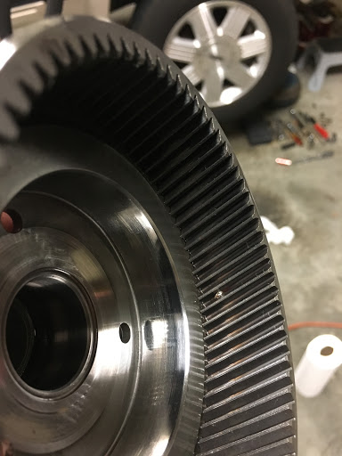
Here is the (OSS) output shaft speed sensor - the reluctor for this one is part of the parking gear.

XOlhhVowvMh3gkXKoNpB9FqDG4OLTEfc29oNqzgJBX7Wnc_twcaPnXfSI-ls2kSvhjWjUslh9KBcRh54BTvbGrVc4-KLhDXv8Eh0YGN4PuCCobMvkJD3z_etzeKMCG1syVzZCQ


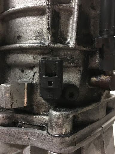
Here is the DTR (digital trans range) sensor - I made a chalk mark before removing the lever to make alignment on reinstall easier.

TmRhb-5atzrgR6QY5OD3MVBRt74y7eYHhmplysNr-q633mVKtlRWbkSw6qNa2dcgsMt2H5hIEd8HoePH740TmBuK5AfKWS4MEJQdg_i02C9GAttgJw2lXjleaRH-0J9ZgP2vYQ


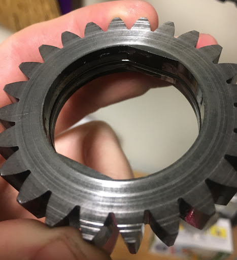
And HERE WE HAVE SOME CARNAGE - after removing the OD band and struts, then the OD drum, then the OD planetary, we are left with the center shaft and input sprag. You can see one of the teeth fell out right away, and the cage is bent and broken.

xhor5AI0ev3lGehzd-vr6b19y1CXbWsHpNm1UznOjpXzmQxXZaddlPwx9TVCpixHtyNNdCjOVMdLfpYzADadELt8E2T8fvB_QNj3D-9AsAA8Mn3ClunuKh6GxX2hpqYx8rrvHQ


Join the Elite Explorers for $20 each year.
Elite Explorer members see no advertisements, no banner ads, no double underlined links,.
Add an avatar, upload photo attachments, and more!
.


Here we have the inner race of the OD planetary - there is clearly some indentions (damage) from the failed sprag. This will have to be replaced again.

EDe2Mj0VsX2CtppdcxjHot_OihS9qYjQNdsQW-Cv6MxBdHVNvtDhiNJaGCc3xXEAY2l6pY_Cyxyqm4C1x-4LmcQeZwKYc_62KUR9WAwPze9rt7PCAOeCeSL7eeeH3Y95lmiU7Q


This is a bit out of order. The star adapter here connects the sun gear (which in turn connects to the OD planetary) to the OD drum. Notice the jagged notches on the edge of each outer 'point'. This is a stationary part though - doesn't seem critical to me, but I may replace anyways.

HFCdEbokJmXWvyQlMp9c9Lv5Uyfr2-8oakNPxQYxLV4wNCcfmqdQ5V2TxG7MaAL09kNJL-y8hLU-2AGwJnyfUNTQpHvQ_pNQQhDNSiPLDBEDUsbBEArXKbm-XQX9sWCuMPPMiw


As expected the OD drum frictions and steels are toasted.

4DnXIJY4NX0SbhfXFPr2FmjtTSs4roREjr5YCiNIKwpB_JnV0RZWB9hZPNEglQjBV_XpOTY_A2dVWPfti4Q7wjuDvT61WmoHSWOqcKK6pG4e6dPgM1636hF_sPknzeN2K5ltog


Here we have the center shaft which acts as the outer race to the input sprag. There is surprisingly little damage to this one. The indentions from failure are there, but are barely perceptible. I haven't decided if I want to replace the center shaft.

JwmZ1R0cc1GOnGNdG4HJrk0UmfHolUaoCND0bimfI3GvJLSyOrAIBLWT7KXqE7xHBYnKQkr9FlwM8KLTqzq_cLY5TJlbHRzNdBEjn7QBOOTcfkV4r4n7jD44WPOpQ2vpM0rRWA


Another pic here of the mangled input sprag.

rYiSQeqDnCMSa5m0MgHmoGvE_1BpwkBUiSUU1Qfd0Fw6YWnjFLMG2K8qQEIimJ5ikwe5S9TAgkJEcFnoGA3uijoaBf_MSMgsbwAvljAtPobF9LgPqg7qJoH-UPeKTtfARcFOqQ


More disassembly. The rest of part in the case looked good to me - although I completely disassembled for the purpose of cleaning debris. Here we have the TSS (turbine shaft speed sensor). You can also see the center support, which is held in place by a retaining ring and a locking screw (3 o'clock).

tqqLo5uXnb2znjM5KMMitLAFJFc78eyhWHD-8wSR5t6trifinVflJ1p5bI6BhJcTdOYTkuJ0JS0JiKMrEFVqVAQE_9OuhzeQqzrqCVp5pAt5h42vxGSwpWHR6gEOJtZHwPyW8Q


Next we remove the center support locking screw which is accessed from the bottom of the case here:

Pe6TbAKJb5KBWWe0s5ilsRknIomR1BoFrhFF_XYYp0tzJHq-0PJWKcKwd6oUPK8hlMAWiHQ0jJAA_e1llXrDHXvqG0ueHE-MlyZiga2OStho5-8K13prDsIJDkAfIwVjzXyTyg


Here we have the intermediate band and intermediate drum. Having gone through this process once before, I didn't need to be so crazy with all the labels. This time I only labeled the bearings so that I didn't get them mixed up.

g8Lf9aUPpkl0saStRJ9bwRWya0Hf1d6rnyrCd7SXsVuswDpdXh2MEovoSSDdLjmzifoBN2KRLVaGxhSpG9pmXvdAJhI0zrmzr_26cvuCJ7RWk5fK62x3rHRwvHuoe1NtHJs3SA


After removing the forward clutch cylinder (missed that pic), we have the forward planetary sitting inside the input shell.

yPLSdNO_j5QO6xk_cfblZtmoSdQ4Qw9HAQzgHKp9HgeW0Za96zBI_1tL839nvvL-fpguz5zSet5LiKDxSWOK84V-LqGef0nUKAVYhDyt9nnTIzLzI--KQRZp7re-9MnRe3x8-A


Followed by the reverse planetary.

-snDHO7Grc6cr6lKo1SlUhTnpIYKAF_gPaJswZwJ_rudLJ_Xil_XwHhc4nHvJwDINdzjb5Tx3GRRToCI0YfQUCIdQ5di1tq6ei7zkxACd_zOjKH9GVI7SMml51ogJfiOxgaBWg


Followed by the output shaft ring gear. This isn't the best angle, but there is a snap ring holding the output shaft in place on top of the ring gear. I was a dummy and the output shaft dropped straight out of the inverted case when I removed the snap ring. Thankfully the output shaft looks fine.

WkTFS-1__dufdBiUWGC9VYUgAJTg60T7p_zeAefv_GLfI_g3mKhi67S21-h_JHn-wjoJuq9OfbAVbNF6J75ayYeS17EQR-3AOUlobeerS_apPxrfx7I8M002J9TtCsdKBv8DZw


After removing the reverse drum/sprag we are left witht the reverse band and the inner race to the reverse drum (this does not come out as far as I can tell). I wonder of you have to replace the case if this race gets damaged from reverse sprag failure... :dunno:

OpWVtCEeuEGFeycd9knP2P0gCm8hGpjZN64Jk4_2EirLP-7qAwwBT8FUq7DYHi92qmG15hmIoITnRsQb4a_T57EIwwTiTU5boZj_B0K_oXBc41jyYqp-kBJ7nA8GpFymKWm5tw


Plenty of debris down there to clean up. No more pics, but after that its pretty straight forward. Unbolt the tailhousing to remove the parking gear and pawl. Unbolt the manual control lever shaft and remove the pin sideways with a screwdriver.


There was certainly a fair amount of friction material debris in the case. I will be much more thorough about cleaning all parts with solvent and air drying. This way I can avoid lint contamination. I will also store all parts on clean fresh plastic and cover to avoid re-contamination from the elements. As mentioned above I'll also perform the extra steps of replacing the torque converter, cleaning the cooler lines, installing a temp sensor/guage and inline filter. Additionally, I will disassemble the pump to clean debris and inspect for damage - pics to follow. I have the plastic pump alignment tool now. I put it on to be sure it fit before disassembling the pump. It was quite snug, I lubed w/ petroleum jelly and still had to tap it down lightly with a hammer and socket. It looks like I will need to rent a slide hammer to get the ******* off. I suppose its a good thing that it is such a tight fit - that way I know it's centered - but it is kind of pain to work with. I guess that's what you get with a cheap tool.


A couple of pics to see what we're dealing with here:

lfvy1XegeAUxfTkjoLYeJ8vvHz3aUIwZZrQ1v6n2keB5XIqRM3pmuQbHYW5lU3DduiD-Mo59GK7oJysJZTgd448ASQFgNz_5EfFtpRFBc2g0RKV-2JBvCt3IYqkR8GZO2X8cfA


MVKqFcWK7c8dTRFGepoaividszWR4yrL9CB7EJyqscg4n_3vjydqHipeaZYZvXI-P3zfPyUFp9KBN2-vaw4m05P805DQTi5uhtkWHS1yUeq-bSfW-_gw2RrqSp1dTnZC2wLv6Q


The pump washer (plastic) was melted a bit. Thoughts on the root cause (other than heat of course)?

WuyUGuaYtfERQWQE0W_k76LJZ_GCSxn9qNyjexCwUQg7-voq9fiv80pjv_unYKhem37_64zBSBJnp7eyOVaanuZ8Zq33xCpNb0UPn0iDw4im0nbw1HljnR_SCQ7LAfdenYxY4w


The OD lube passage appeared clear. I cleaned it out upon disassembly and did not observe any debris.

djWijhz3F9G3HHlj135HTpG1JBkZMMDdjNdvHwgXEC1g9MkIMKNtZUDTLDPpAbdxtiqEJXCrVAMrvlGczEnyOOVmNPJ2VHGr8rqImsw0DHoXxsQuDhJhrsUc98kBMjBqLmOnOA


I really didn't use much force at all to seat the plastic alignment tool initially, yet it got completely stuck on the pump shaft. I ended up having to melt the plastic tool with a torch to get the :censored: 
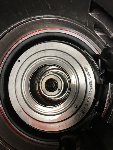
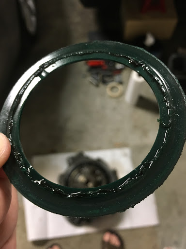
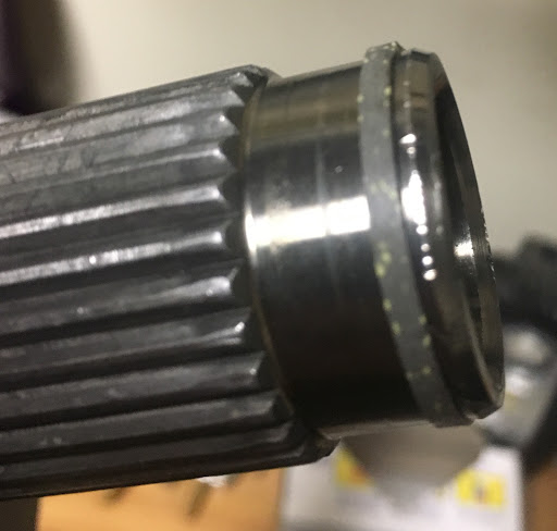
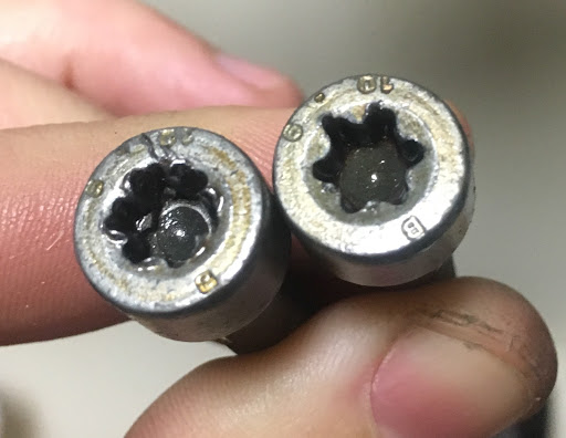
pump apart. A closer inspection of the tool - you can see the writing on the lip in the pic below - shows that it was in fact designed for a W-N-S version pump, not the E. I was under the impression that the W-N-S used the same torque converter as the E, and hence the pump shaft would be the same, but perhaps there is a slight difference, enough to give me the trouble I had. As you can see, I didn't drive the tool all the way down, anticipating that I would need to pull it back up by the lip - but it simply would not budge. I then proceeded to unbolt the pump and drive the shaft down through the housing, using a large socket to protect the tip of the shaft. Again it would not budge until I took the torch to the tool. I will have to find another tool that fits properly for reassembly.

syh4fNzfhJS31fGNNEtJIhyZvEUl3BdDGPrxldt2Lo5-Uso7llsaZ1MmtVZQ-Xo1AXOMcOEIXR_7gs5axnXZ-HpiKg-Zb0M03Sj3DjVggm6gZdo8397JGJa-hx3tHgg8pSNtrA


You should not have driven the tool down that far. Take the 6 40Torx bolts out of the stator and put a block of wood on the stator shaft and tap it with a hammer down through the bell housing to free the tool.


Here we have the adapter (wear) plate. It sits between the pump and the bellhousing. The shiny area is where the pump gears ride. This does not appear to be overly worn to me.

k2vPMCBN1xMu7lvt6NiSye6GMA3P6ha8D98QX_6HXShpUM82Drm0TgulsegEmpO_8dvRdcw75d9NgvU58lcJ9N0mdab6DEb9N_XR7xp9UDHneGhpg-KSVVC_sGRJr4BokTw51w


Here we have the small pump gear. There is a seal on the inside of the gear. The top edge certainly shows some wear lines, but I wouldn't characterize it as damaged. One side of the inside edge of this gear is beveled (facing down in this pic), the bevel goes up upon reassembly.

XxB469Ljs6EgNQgKEgV1vEarD_q06UpxLixOUxN-i84UjOkEXnHGycSeCK_RbN2LqihqE9UAnYQB80wo5R-pNe_KROEWLq0B-15ntx4SCgBHIkeJjRPEoofU3lctioqOX9VPKw


Although I did notice some nicks in the metal on the inside edge below.

oT5q3n2_HT4OC89XDtmQV0b_ko5V1qfKT9TuIY2I61_FmWvOrm0XI1FWEgej43AXcT93f8MrtOAxhokpr1OcRcJ6J89vxX7a9BXqAl8DHYSp0Mqwj8dC5O9XWZqgEEN4pl-Oug


Here we have the outer pump gear. Similar types of wear lines on the side edge. There is a dimple that goes down upon reassembly.

Q8PzXnaAqXfZJ-osV8AOfPLpnm2xLbX-DjhnjNVt0uYILtlJi-hPpdnNp3xPZhlo8sLZpC1I5-kdsKIvOx8v0TCcuV2Wj1QKFejzku7hBSdNuMyv04MeEtv4ojWAcORshTOLyA


There is a noticeable notch in the pump shaft. Is this by design? Or is a sign of wear, which would require replacement?

WPM0gumCPV1hkzhHiTSdShI0V0ibzzZSxKGub3nudxiX2bgBJvxKpHjFEOu62Qp7VsXIY2f__VIcroPr7EuJJ9r6nJto006bJiyq-Y0JPmhzf7x4_VDKxyd0McTWQgFEUXWUIA


View of the underside of the pump, disassembled.

c9rkmWKii4Y8c4lbiW2CioBzJKalabPcjGrZpHUYNTJWPb4snht-TqedF2eR7iZFkh0zUgsC4u-c5p6HUQEHIqyH9GUFng--Xc9utEUhTeyPwDA7iHVlYKJnRPYOB7yp27JP1Q


The seal at the tip of the pump shaft seems to show some signs or age. This seal looks like it needs to be replaced.

GzIInzQe5AyPZCYi10FfbHPBa3vsWTplA0v6E-gsIpCneL2e5DpiGFciwdKaahWYdLeO4AzOE60VI8D1o37Mgqx2d9nZk3W-1hvzVo0afZ7UgbUdMtkIU2ZJVGSlTJ9zGn29Gg


A view of the top shaft bushing (gold color). Brass maybe?

y2qg6FATInJluahXM2dW4VBiq5mJTH0CGbG8oV8jewB5qfN7CvdjjTn4NPRnlFnPx_pbklcMEjdK_o-i1r0uo1LfVF2Jnb91VhAKNXg-qNLKGvlyN2qWxWJI4WEkAWzSfXNDuQ


Close up of the cleaned out lube passage. (2 o'clock)

0AklltairklUNUORkp0Fm9uYgcuzcVLk7g-UrMLx8-hz9tDrzRkMvhAg4VzixM1XkFs5eNLKz6s8q3uFsBlfT8Ej_7e7u32vOQUhfEuvmzzmsp8bI2Xnhml5ghJgfMAr7QD0DQ


A view of the bottom shaft bushing (gold color).

yoNkCQEHumdsH1Fm6Ikcb4Vne588JSwsD2S3UAsSCnCwZYJe3vb5gAVbunirm1jsZFvnDVNe4ruW_rrHjZ3HoKCmpWATxOlSHQP_7Z4Iynb9bDiNJznZQBvu2kzcIU0mUGbtog


Here we're looking at the side of the pump. I've seen on a few other trans pumps that there is a removable check valve known to go bad. I don't see anything like that on this model. The ends of this pump kind of look like check valves, but none of them move (I doubt I have4 stuck check valves).

yVNV5mtIxPjC-UrqPqi4P1Z4qYXjWD3iI5uHsYKyGshKI9ldKJwuiLuA0dwu89Xvfu946RmIxdnSfK9SDHpGbElGc67ZlTDS_3ntcsYJaeMkM9bV1AauXkhL7wB5yYB9RHa_ig


Here the pump gears are in place. The bevel on the inner gear is correctly oriented (towards the torque converter), however the outer gear is actually upside down - the dimple on the left should be down (away from the torque converter).

3My8cGD_pjessZJIeE24-r1shDAQUMcwcjCzV9FdTU3bzwk3XDlX4MxRGM92uMR_v2OzhcDpKzsaob9M9zE4NCjU1zJ-Am_b0tAcYGwnPjWOFtIG-A2Z-yOstF5P1QAVlMhj4Q


Here is a closeup of the bellhousing bushing. There is noticeable notch cut in this bushing. It appears this is from the factory, as it is too clean to be the result of damage. Is this right? My understanding is that if this bushing is damaged, the bellhousing must be replaced.

D05hqeKLUvJDzKy-g0PgaBjNDGvUd5DbmaL1zCcSrSDwuzPOSlhhsrarmIQkt2t2A5mo3khonmRzIBTIHy89VL5P_y-9_rdYsfxNJLEVElx5epRtRqeShvwagyE_PN3vQeYm7w


Another view of the pump with gears inserted.

LdmdxNJBI7SaPrM7Ibq0p3xl7IbO2_sRFBicjYktq8ZQo9p9t7uQ3KeJHsFyqVyu8IygROdsG2C12eLt5E7KbOz7We1Nin7mJrpsfLu3sxvczGrEb9rX1HNxQRGuxk7ZoW-Jzw


A quick note on the T40 bolts which secure the pump. Mine were torqued down extremely tight. First I tried by hand w/ a ratchet and they wouldn't budge. So I pulled out the impact and promptly snapped my torx bit, partially stripping the bolt in the process. So I got a new bit and successfully removed the bolts using a breaker bar. These things were so tight the new bit started to deform - twisting somewhat. I barely got the stripped bolt out by making sure I was completely seated in the bolt by tapping down with a hammer. That bolt will need replacing. If your bolts are stuck, my advice would be to use a breaker bar or a cordless (less powerful) impact, and make sure the heads are free of debris and the bit is fully seated. The torx bit really is not designed well for a large amount of torque.

DDM7124__7Rzgrf1N54bpasckyV0fNSLG21DicQCJH2yo4CNMGv8nSdlqgv1FVfvTIj0Sjc1_6MnF7EJXk-03R89oCevV4dDai6lwfr80Fqy-wDEpvOgZBw5kCaimu8kG_P5pw


My used replacement OD planetary arrived today. Trouble is the reluctor is bent:

v3kxs_z7HDzZNyZpKXu76QC7sSd8LEhqescH6KVbjp4SH5ZRLA.jpg


What do you think? Should I try to straighten it out or send it back? Not sure how sensitive the sensor is to a wavy reluctor.


You can straighten it out, I have done that a few times.


I'm with James on this,you can straighten and check the air gap at each trigger point between TSS and reluctor. Need around a .030 gap. Not real picky. Good luck.


Just saw the picture of the melted thrust washer. That was caused from end play was to tight. I will try to get some pictures put together to show an easy way to set that.


I figured that end play was the culprit on the pump washer, so I got a thinner washer this time. The book has a procedure for checking end play at the pump that I can now do with the pump disassembled this time. The closer I inspected the pump stator, the more I realized how badly scored it was. So I ordered a replacement. I also got the metal alignment tool. Interestingly enough, it won't go all the way down the stator shaft (no wonder the cheap plastic one was so much trouble). I'm guessing this is likely due to the scoring. We'll find out when the new pump arrives. More pics to come on that.

What do you guys typically do when cleaning the valve body? Do you fully disassemble it? Or do you just clean what's visible? I have no reason to think the VB is bad, just thinking about the possibility of contamination.


The only way to clean it is by disassembling it.


What do you guys typically do when cleaning the valve body? Do you fully disassemble it? Or do you just clean what's visible? I have no reason to think the VB is bad, just thinking about the possibility of contamination.
It sad that you have to go through transmission rebuild procedure ones again.
From my experience of VB cleaning i learned not to use the paper towels to wipe it. These towels loose it's fibers and it was very tricky to "fish" them out of VB fluid passages. Crows foot lint free solvent wipes is better, but in an ideal it just small brush, solvent, and moisture free compressed air. I used as solvent HiGear brake cleaner and ABRO carb&choke cleaner, which is clean and degrease much better, but it may be aggressive to rubber o-rings or plastic, and require instant passivation with WD-40, i used this one for valves lubrication. But unless you have heavy VB contamination, or jammed valves i would'nt try to clean it completely. This procedure is extremely delicate, VB have many small parts inside, which may be lost, and "L" pins that can be mispinned. Thats thy i confined my VB cleaning with fluid passages, solenoids, TCC, EPC screen, and jammed cooler limit valve.


It's been a little while since I've had some time to work on the 'ol sploder. I have all my parts and supplies, and am about halfway through the rebuild process.

Right now, I have the valve body mostly apart:

B3mk8jh-XSSrxdTffKj5Bv9uWbOJq2Dk_S1M5mS8InPOWWbJtmpAA1imzlDNfr5XtfBg8-iwQ_hurwLYCfNEkO4V3kxby0qfpjid1-Suk2nb8PqhpX5BbTvs2uuODDFwDJJ3hQ


Here is an overhead view of the VB while still assembled:

qCfUnjmGw3Efhv3tIh2jabg3OaBrB2DQ-3r2TnuX3lYICFbvrbPkqOeTb65HWl-zK6WucCG4dVtvepnfIbza2jtf-q0I4_USNCF_sskDmvvbrbg5ouS9hT9f5Plv_H6Ak363uw


The red lines below indicate bores that I am having trouble removing the plugs/springs/spools - actually getting an accessible area to prod the parts out is proving difficult. The green lines indicate two locations where it appears Central Valve Bodies (I bought this unit reman from Central last rebuild) has removed a spring - at least according to the parts diagram I have.

gKmQxSZ5Y9Gv7xt77tXpeUCpaThhX5KJ8aCr0BxCuvAkrDahM01ZJdJq3aNa1ykGYH0GNEW_HlsSdsjyavrhA2ma1pxokpVNBjwQCsLZz2LZYVrkExF1NqqM6x4_nbT2Xw3O0Q


Here is the exploded view:

V5Jsb0JeSAXESL0CvkMX9Q2HBEjxPlNKVdx8T2dVlWXx_6_1Q_xnN2G4uIVVNazb-F3SwvkSc36PPrsgNEX_CDvZzv9-qadL5vz4jsJinqPAdEz_pUIoairYotpsCqaASaZqCA


And the parts list:

YCQEgxOSqUEPLkQtqEEF7QGcg0rvpKcp12jqzVcAULvVu7u5XHM-KWtetTupDU9-aPL4E1q7Bx4AQgmo2K1p2nyIhCRcwpGMy8Hf7Q0AQx-Ws749AivzhLoNEI85DBCH0poopw


And a few closeups of the springs/spools/plugs:

In this photo the bore on the left should originally have had a spring - part #35 (cooler limit) - between the bottom two parts.

lJgRfCyIvTnhPEkqXpALm5KfGnLF9VxYCXqvuftQyLLIRxI7GSkmf_WlqC_7bYOoroOND4ekEHpwwWBTgo9763ZkffkOykVA8g5cuVef2ZzhE8aDHIZWZq96hhRK1tHXSiY3XA


In this photo the bore on the top should originally have had a spring - part #18 (forward engagement) - between the spool and the plug. I'm having trouble removing the remainder of the '3rd from top' bore parts. I also have no idea how the manual valve is supposed to come out (very bottom).

UGJsZt0idWpX44xoRmvuMRHHJU3Dl8FwgwQjrq8dp5PCYWkjo1TavAIEF0Q8RWstfWuJfDN3LsZIbSl2JZptsP-PfOMqbRl_zGR7Tb_4oKwJ6ACXPaTzC324LUevuRYFvnyM8w


And here we have the 'bottom bores'. No missing parts here, but I am having trouble removing the 2nd and 3rd from left bores (yes, I had the pins out), due to lack of access.

tTQk1xEklbUHWdCxemTkdh8fGO0jP2kpCVQA68nHLmvKqyg_6w_g1f6NJ7n1cjkisIwAE-K28fiqGw3mH7XFaOKWxsyEr_waN67bSFm7IwfXdCjFbVxVDeeW61drSRWsZ7Eg-A


The sole purpose of disassembly here is to clean and inspect - no mods are being performed. I haven't found any debris at all, a few spots do have some dark residue though. What do you guys make of the missing springs? The cooler limit spring I can understand as a mod to keep the trans cool, but no forward engagement spring? That one has me scratching my head, and may explain the clunky engagement I experienced shifting from park to drive. Any tips of the trade to get the other bores out? So far I have been using an assortment of mini flathead screwdrivers, straight and angled picks, and a paper clip for the really tight spots.


I think you right about the cooler limit spring absence, it may be mod to keep this valve permanently "opened". Looks like all check balls and lube orifice in it's place, can't see EPC circuit limit screen. As far as i know VB valves should come out easy by their own weight, without rough force applying. Pay attention to correct "L" pins positions, pressure boost sleeve (11) holes orientation, and (13,14) springs coaxial alignment during reinstall, i heard they should be tacked in place with assembly lube to hold in right position.


Join the Elite Explorers for $20 each year.
Elite Explorer members see no advertisements, no banner ads, no double underlined links,.
Add an avatar, upload photo attachments, and more!
.


what exactly is the correct orientation of the holes in the pressure boost sleeve? Let's say we are looking down from the top, which way should the holes be facing?


Back
Top