I'd bypass the wiring at the relay and add each part of the circuit in one at a time till the problem reappears. Spade connectors, wire, inline fuse and a switch.
#30 is the battery + supply
#85 is the ground - return
#86 is the switch, which comes from the eec
#87 goes to the pump
According to a previous post by Roadrunner777:
Where are you measuring the 10V exactly? Which wire, which ground? If you can read schematics, you should be able to solve this with the diagrams I am attaching.
Here is the current path from the battery to the fuel pump:
Battery + terminal ->big red wire->starter relay lug->big black wire->Power Distribution Box
Power Distribution Box->Fuse#18->Fuel Pump Relay
Fuel Pump Relay to PCM and Inertia switch (both Dark Green/yellow wires)
Inertia Switch->Pink/black wire->Fuel Pump->Ground return to Battery
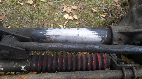
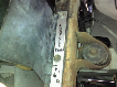
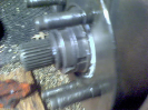
Thanks for the reply. Here is something I found quite handy, I took and old relay apart and removed the spade connectors, you can then use them and jumpers to plug in to the appropriate connectons in the power dist. box and
test the relay and measure voltages with the relay in your hand. That is what I did and like I said, when I measured between #30 and ground I got 13VDC, I then measured between #85 and ground and got 13VDC I then measured, I then measured between #87 and ground and got 13VDC---these were all measured from the power dist box connections with the relay
out.. I then used the jumpers and spade connectors ( I took from the bad relay) to hook the relay into the appropriate lugs(like it would be plugged it). Then measured again. This time measuring from the lugs connected to the relay with the #87 still unplugged and hot. At the relay #85,#86, #30, and #87a all had 13VDC and #87(at relay) was NOT hot, So from what little I know this didn't seem right. It is now in the hands of a mechanic and we will see what happens. Thanks again everyone.....the debauchel go on.