Aaron's Mountaineer: Massachusetts | Page 4 | Ford Explorer Forums - Serious Explorations

  • Register Today It's free!

Aaron's Mountaineer: Massachusetts

Aaron "V8BoatBuilder"s Elite Explorer Registry Page

IMG_0973.jpg

Rausch Creek Off Road Park, PA. 33" Tires, 4" Lift

13422IM001322.jpg


13422ccmounty_web-med.jpg

West Dennis Beach, Cape Cod, MA. Truck as purchased, Christmas Eve 2002

13422dsc00439.jpg

Got lost on the way to the mall..... Offroading in New Hampshire. November 2003

Introduction
I have set up this thread to detail my modifications, provide some step by step instructions for many of them, list my tips for general maintence procedures, and even throw a writeup or two of anytime I decide to subject my truck to the abuse of off-pavement driving.

I strongly encourage all members of Explorerfoum to read this thread, or skim over my dry writing and just look at the photos. Hopefully you can find a usefull tip or learn a little bit about your Mountaineer or Explorer. If you have a question, feel free to PM me, or even post it here. I've edited many posts to reflect conversations I've had over PMs. So yea, check the "older" posts, since I sometimes update them too..... (I have way too much time it seems....)

Now the Disclaimer:
If you follow any of my writeups or tips, I take no responsibilty for damage or injury you may encur. Always double check your work, and make sure everything makes sense. Never work under a truck that is only supported by a hydraulic jack - use jack stands! Remember, some systems, such as brakes, can affect others if you are not careful. Have fun, and get greasy. Make that truck your own.

Specifications As She Stands, 1/19/08:
Year, Make: 1997 Mercury Mountaineer
Color: Black, with gray trim and body cladding
Engine: 5.0 Liter 302cu in. V8. GT40p Heads.
Battery Duralast Gold Grp 65 Wet Cell, custom wiring
Transfer Case: Borg Warner 4406 Control-Trac w/Torque on Demand and low range.
Front Drivetrain: Dana 35 SLA, 4.56 gears, Open Differentail, Center Axle Disconnect
Rear Drivetrain:Ford 8.8" 31 Spline, 4.56 gears, Track-Lock Limited Slip
Tires: Interco TrXus MT 33x12.5R15 on Cragar 15x8 Chrome Plated Steel Wheels
Interior: Gray with Leather and Mountaineer stitching
Options and Creature Comforts Power Seats, Alarm system, remote keyless entry, power locks, power mirrors, overhead console with Autodim mirror, outside temp, compass. Rear Air. Message Center.

Modifications:

Page One (You are here)
- Ford OEM Class III trailer hitch installed 1/10/03
- Rancho 9000x 9way Adjustible shocks installed 2/14/03
- Aux reverse lights installed 2/15/03
- Oil Pressure Sender conversion in progress 3/14/03
- Front Tow hooks installed 3/31/03
- JC Whitney Full Brushguard installed 3/16/03
- Hella 500 Driving Lights installed 3/17/03
- Audio System including: Pioneer MP3 headunit, Pioneer 12 disc changer, Alpine v12 Mono Amp, Dual 10" Rockford Fosgate Subs (Now removed), Sound deading insulation installed 3/18/03

Page Two
- Explorer Express Swaybars installed 4/13/03
- MAC open element Air Intake installed 8/15/03
- Ventshade VentVisors installed 8/15/03
- Custom made Stealth Subwoofer Box with Kenwood eXcelon 10" DVC woofer installed 8/17/03
- Warrior Shackles installed 11/20/03
- Aux Transmission Filter Installed 12/20/03
- Autometer guages (oil pressure, oil temp, trans temp) Installed 12/21/03
- Torsion bar adjusters, January 2004

Page Three
- 2" Front Lift from TT, Add-a-leafs in rear Installed Janurary 2004
- Front control arm Camber Adjusters, Installed January 2004
- 31" BFG AT KO tires Installed January 2004
- Custom Front skidplate, February 2004
- New head Gaskets and a Valve job, June 2004
- Accell DIS coils, Taylor Ignition wires, June 2004

Page Four
- Baumann Engineering Shift kit and other 4R70W Mods, December 2004
- Message Center, January 2005
- Torque Monster Headers, March 2005
- Cruise Controll Deactivation Recall, June 2005
- Control Trac/4x4 trasnfer case swap, June 2005

Page Five
- More on the 1st BW4406 swap EVER!!

Page Six
- Waterpump, Timing Chain, Timing Cover, Cooling Hose Replacement
- Superlift K494 4" Front Lift, Central Axle Disconnect Swap
- Custom Stainless Steel Braided Brake Lines
- Rear SOA, 4.56 Gears


Planned Mods...
- Custom Rocksliders
- Custom Rear Bumper w/Tire Carrier
- Fatmat entire interior
- Sandblast, POR 15, and paint underbody, suspention and frame.
- Replace rear leaf spring bushings with Energy Suspention Poly
- Lockers
- A Pillar grab handles
- Flowmaster Exhaust with 50 series delta flow(s) with dual 2.5" piping or single 3", custom downpipes and high flow catalytic converters.
- Upgraded door speakers and amp
- SCT chip w/87 octane program(s)
- FMS E303 Cam and Roller Rockers
- Cut the roof off and put in a cage!!

Help.... this list is getting too short!

These photos were taken the night I purchased the truck: (Christmas Eve 2002)
13422aaron_s_mountaineer2.jpg


ENJOY THE THREAD!


Join the Elite Explorers for $20 each year.
Elite Explorer members see no advertisements, no banner ads, no double underlined links,.
Add an avatar, upload photo attachments, and more!
.


Baumann Engineering 4R70W Shift Kit Install

I haven't done a "how-to" thead with photos in a while, mostly because I've been at work or in school and unable to wrench on the truck. I've wanted to install the Baumann Engineering shift kit for a while, and finally ordered it and put it in. In addition to the shift kit, I ordered their torque converter application valve update for the extra $30. While I was in the valve body, it made sense to do it. http://www.baumannengineering.com/

Based on a few threads on here, I decided to set my 1-2 shift to stage "2" and the rest of the shifts to stage "3." I spend a lot of time in stop and go traffic, and also in the snow and ice. I didn't want to spill my morning coffee or break traction on the often used 1-2 shift. More on shift selection later.

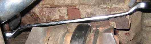
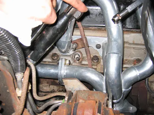
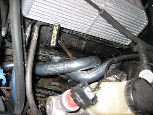
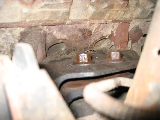
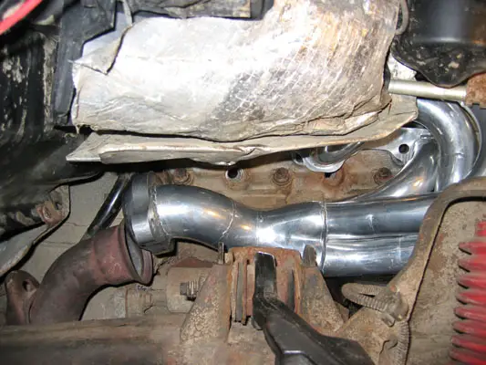
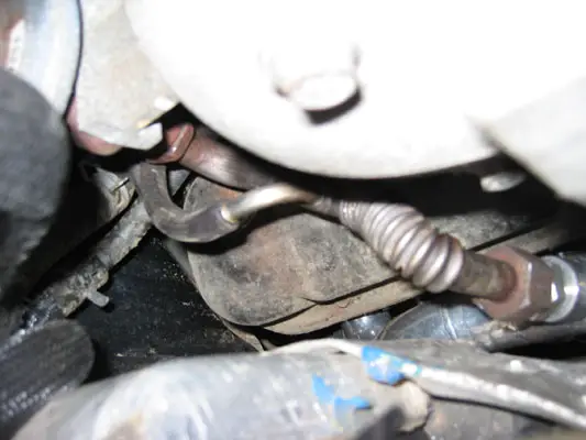
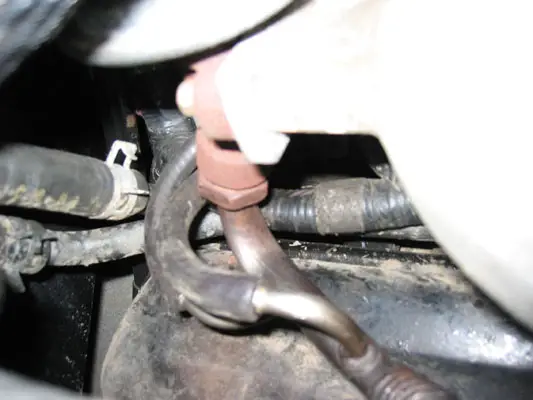
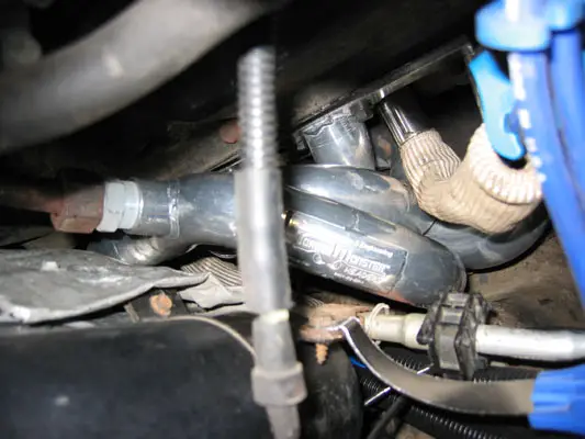
I started by draining the transmission fluid and removing the pan and filter. Last year, I had installed a transmission pan drain plug, came in handy this time around:

1342201Tranny_Pan_inside.jpg


1342202Tranny_Pan_outside.jpg


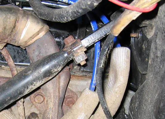
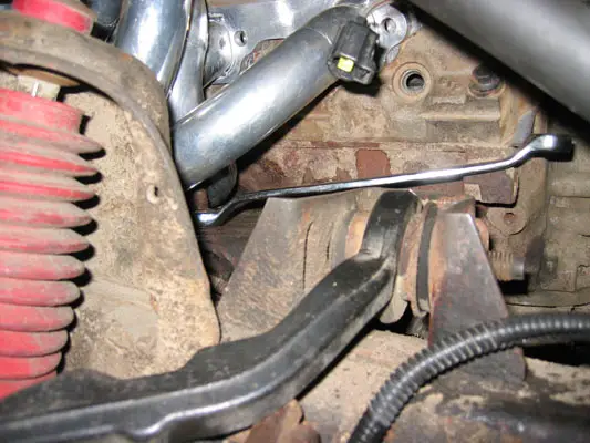
I took out about 9 quarts of ATF, and refilled about the same. Only 5 came down in the pan, the rest came slowly dribbling out as I dropped the valve body. I disconnected the electronics, and then removed the 25 8mm bolts that hold the valve body to the trans body. Two of them also hold brackets for the shift selector. I removed all but 4 bolts, and then let the valve body hang on those bolts while I held it in position. It's very heavy! If the valve body doesn't drop onto the loose bolts, you most likely missed one. The gasket's don't have enough pressure to hold this thing on. There are no linkages holding on.

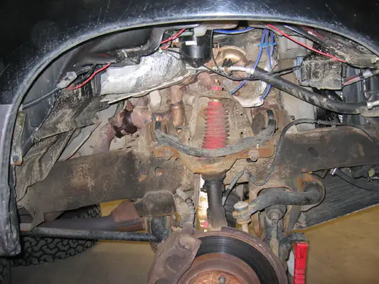
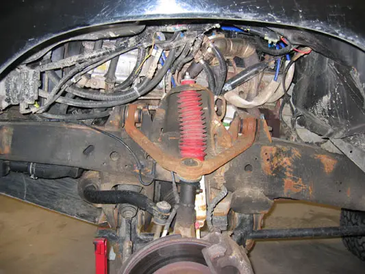
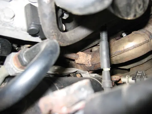
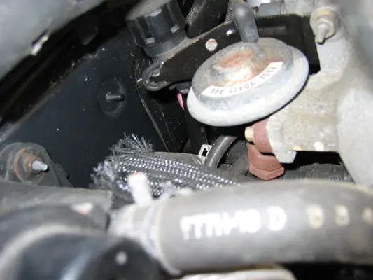
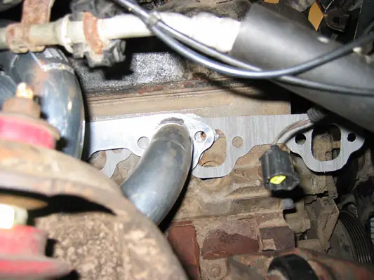
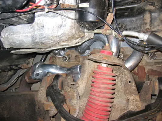
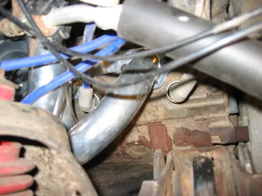
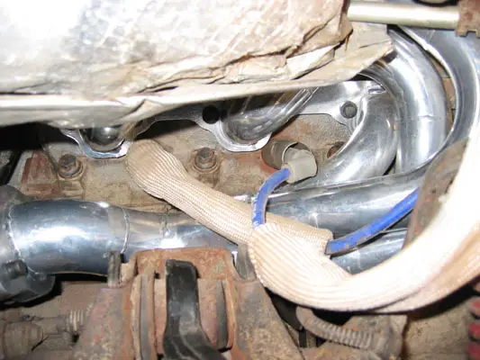
Here is a photo of the underside of the 4R70W without the valve body:
1342203-4R70W_without_valve_body.jpg


The valve body removed from the truck and on my workbench:
1342204-Valve_Body_underside.jpg


1342205-Valve_body_topside.jpg


I've found borrowed dining hall trays invaluable for work on the truck! Once the valve body was on my bench, I removed the sperator plate.

Valve Body Disassembled, seperator plate removed:
1342206-Valve_Body_disassembled.jpg


Seperator plate gaskets:
1342207-sep_plate_gaskets.jpg


Included in the kit is an awesome instruction manual, some Baumann parts, and the Sonnax parts I ordered.

Sonnax and Baumann transmission parts:
1342208-Sonnax_Parts.jpg


Baumann supplied drill bits:
1342209-Baumann_Drill_Bits.jpg


Keeping the drillbits in order is very important. We're working with super close tolerances here. Once I selected which shift levels I wanted, I cleaned off the ATF from the sperator plate with brake cleaner, then marked the seperator plate with Sharpie. I didn't want to drill the wrong hole! The drillpress was invaluable here.

Marking the seperator plate with Sharpie:
1342211-sharpie_your_sep_plate.jpg


Drilling the seperator plate:
1342210-drilling_seperator_plate.jpg


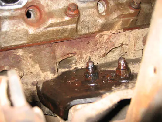
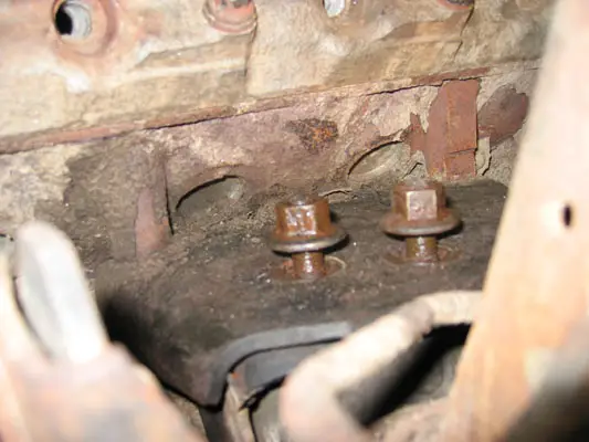
In addition to drilling the seperator plate, part of firming up the 1-2 shift lies in the 1-2 accumulator. It's in the transmission body, but accessed from below. It's held it with a pretty beefy snap ring, so use real snap ring pliers and wear saftey gogles. A spring is replaced, and some shims are added. Pay attention to the late model 4R70W instructions here, things have changed since the AOD-E.

Ford original 1-2 Accumulator assembly:
1342213-Accumulator.jpg


Baumann vs. Ford upper accumulator spring comparison:
1342212-Accumulator_spring_comparison.jpg

(The Baumann spring is the silver one)

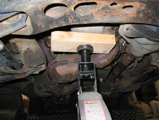
Compressing the 1-2 accumulator to re-install the snap ring was proving to be a challenge, untill I put my bottle jack on a milk-crate to hold it in place while I reinstalled the ring.

Re-installing the spring loaded 1-2 Accumulator:
1342214-Accumulator_Jack.jpg


After that, there were some valves replaced or shimmed in the valve body, and then the body was re-installed into the truck. The torque converter control valve from Sonnax also detialed drilling another hole in the sperator plate.

I cleaned everything with brake cleaner, then pre-lubed it with ATF before reassembly. It was hard to keep it all clean.

On my first test drive I was impressed, but the shifts weren't as firm as I would have imagined. The transmission seemed crisper, and more solid. Downshifts were improved also. If I had to do it over again, I might have gone stage 4, but time will tell. In the explorer 4R70W, many of the passages are already enlarged from what Baumann says that they should be. Since the seperator plate holes are a mater of relative size, I think our stage "3" is a stang AOD-E stage "2." I could be wrong here.

I think it was a good, worthwile mod. Took about 6 hours to complete, including a lunch break. It ended up costing close to $200, the kit and extra parts were $150, and 10 quarts of Mercon V isn't cheap.

The original write-up thread can be found here: http://www.explorerforum.com/forums/showthread.php?t=123942


Join the Elite Explorers for $20 each year.
Elite Explorer members see no advertisements, no banner ads, no double underlined links,.
Add an avatar, upload photo attachments, and more!
.


The things you do when you're bored.......

Good work, my friend. Remind me never to eat at your dining hall. :)


izackary said:
The things you do when you're bored.......

Good work, my friend. Remind me never to eat at your dining hall. :)

Those dining hall trays are an awesome shop accessory, great for containing parts, fluid, and tools. Oh... they're also good for sledding too (which is why I borrowed so many from the dining hall in the first place) Milkcrates are another accessory that I've borrowed, and can't get enough of. :)


Torque Monster Headers: Installation Writeup and Review (1)

Notes:
The original thread for this modificaion can be found here: http://www.explorerforum.com/forums/showthread.php?p=1157284

Introduction
I spent the past weekend installing a new set of Tech Performance and Engineering's Torque Monster Headers on my Mountaineer. This post and thread will evolve over the next few days as a photo-documented "how-to" guide on installation of the headers, and a subsequent review of how they fit and how the performance of the Mountaineer has been increased. I will be editing this first post as the installation guide, the second post will the review. After that, let the comments begin!
13422TM_Header_Logo.jpg

Welded on TP&E logo, pass side header

Why Headers?
I had the stock manifolds out of the truck last June for my valve-job and head gasket repair (see: http://www.explorerforum.com/forums/showthread.php?t=108712 ) and could not believe how restrictive the design was. I had wanted headers at that point, but they were impossible to find. I am also always looking for bolt-on performance mods to increase the V8's power and/or gas mileage. While a supercharger may be the "ultimate" bolt on, bolting one on a 8 year old, 125k mile engine isn't the greatest recipe for reliability. A cam swap would mean discharging the A/C and substantial downtime. Headers on the otherhand, can be bolted on in a weekend, will increase power, and will not harm reliability. They are also a part that can be grown into, should I decide to cam or supercharge down the road (and would be a necessity anyway with said mods.)

Although the FMS headers were just re-released, they are very close in design to the stock manifolds, while the new Torque Monster headers are a much cooler design, with some neat technology behind them.

Tools Requied
Besides the usual compliment of wrenches, a few speciaity tools are needed. Don't make emergency parts runs like I did!

- A copious amount of 3/8" socket extensions and a good u-joint.
- 1/4" to 3/8" and 3/8" to 1/2" socket adapters.
- A good torque wrench.
- An 18mm offset wrench, for tightening the engine mount nuts.
13422offset_wrench.jpg


Installation
(You'll have to excuse the salt, dirt, and surface rust. The weather has been really bad up here in Boston latley. Stay tuned for the big underbody painting thread come springtime.)

1) Jack up the truck, and support the lower a-arms or frame on jackstands. Remove wheels and fenderwell linings.

1342201_Pass_Fenderwell_Removed.jpg

Passenger side fenderwell removed
1342202_Driver_Fenderwell_Removed.jpg

Driver's side fenderwell removed

2) Remove the 13mm bolt that connects the steering shaft. This will allow the lower section of the shaft to be rotated out of the way during installation.

1342203_Steering_Shaft_Bolt.jpg

Steering shaft bolt

3) Remove all ignition wires and sparkplugs. Take the wires, and any mounting brackets completely off the engine. You'll be re-routing them once the headers are installed.

4) Remove manifold to downpipe bolts. There are two per manifold, and can be a pain to reach. U-joints and long extensions are a must.
1342204_Driver_s_Side_downpipe_bolts.jpg

Driver's side downpipe to manifold bolts. View looking up, camera placed next to front driveshaft.

5) Begin to remove the driver's side exhaust manifold to head bolts. Some are studs, some are nuts. The dipstick, bolted onto cylinder seven's aft stud, just pulls straight out from its hole in the block.

1342205_Dipstick_Tube_Assembly.jpg

Dipstick assembly

6) Remove the driver's side exhaust manifold. With the steering shaft pointing vertical, it will wiggle out underneith the brake booster.

1342207_Removal_of_DS_Manifold.jpg

Removing the driver's side exhaust manifold, side view

1342206_Removal_of_DS_Manifold_top_view.jpg

Top View

7) With the manifold removed - compare it to the new header. My jaw dropped. :)

1342208_Driver_s_Side_Comparison.jpg


1342209_Collector_Comparison.jpg

Collector Compasion, stock stamped vs. TM Modified Merge

1342210_Stock_DS_header.jpg

1342211_stock_DS_ports.jpg

Stock header

1342212_TM_header_ports.jpg

Torque Monster Ports
1342213_DS_Manifold_Removed.jpg

Driver's side manifold removed

8) Install driver's side header. The header comes in two parts, allowing easier installation around the steering shaft and fuel lines.
a. sperate the #5 cylinde tube from the header.
b. Insert the main header piece at the rear of the motor.
c. Drop in the #5 cylinder connector.
d. put one bolt in each header peice, then bolt the two together. It is important to loosely bolt the headers to the head before bolting the flange together.

1342214_DS_TM_header_installed.jpg

Completed driver's side header

1342215_DS_TM_header_top_view.jpg

Driver's side Torque Monster Header top view

9) Re-attach dipstick. It will just press into fit, and then can be bolted down with the other 8 header bolts. Normally, a threaded stud will hold the header to the block, and the dipstick will be bolted speratly to the stud. However, the header tube is so close to the stud, the larger nut will not fit on. My dipstick is temporarily bolted below the stud's main nut, untill a smaller nut can be obtained.

1342216_Dipstick_re-attached.jpg

Dipstick re-installed

1342217_Dipstick_top_view.jpg

Dipstick top view

10) Torque down all 8 header to head bolts, and the two flange connection bolts. Do NOT connect the header to the downpipe at this point, flexibility is needed when the motor is subsequently lifted from its passenger side mount.

11) Begin to disassemble the passenger side for header installation. Disconnect the MAF, IAT, and crankcase breather from the air intake tube, then remove the intake tube. Remove the air filter and MAF. Lastly, unbolt the bracket that supports the MAF/airbox and the foglight realy. Put it aside, there is no need to remove the foglight relay.

1342218_Airbox_Bracket.jpg

MAF support bracket. I have re-located the climate control vacuum reserve sphere to the upper fender, rather than have it be attached to the fenderwell lining. This 'mini-mod' was done last year during my aux trans filter install.

12) Remove the lower EGR tube-to-manifold connection. I used an adjustible wrench, as none of my combination wrenchs were large enough. Your miliage may vary.

1342219_Lower_EGR_nut.jpg

Lower EGR tube-to-manifold nut


Torque Monster Headers: Installation Writeup and Review (2)

13) Remove the EGR vacuum hoses and the upper EGR nut.

1342220_Upper_EGR_nut.jpg

Upper EGR nut

14) Remove the passenger side manifold-to-downpipe connection. I have liberally applied PB-Blaster to the bolt threads.

1342222_Passenger_Manifold.jpg

Passenger side exhaust manifold

15) Remove the 8 manifold-to-head bolts, then remove the manifold. On the passenger side, the manifold is removed through the front of the engine compartment, above the A/C line and below the airbox's normal location.
1342223_Passenger_Manifold_removal.jpg

Passenger side manifold removal

1342224_Pass_manifold_removed.jpg

Manifold removed

16) Comparison shots! Unlike the driver's side, the passenger header is one peice, and the tubes are almost equal in length.
1342225_Pass_comparison.jpg


1342226_Pass_Comparison.jpg

Passenger comparison, including port size.

17) Since the header's tubes straddle the engine mount nuts, the engine must be lifted 1" to allow the header to clear. The engine mount nuts are 18mm, and heavily torqued down. I used PB-Blaster, and a deep-well socket. I put a 2ft breaker bar (steel pipe) over the end of my Craftsman ratchet to gain enough leverage to break the nuts free. Notes:
a.The driver's side mount does not need to be touched.
b. Section525 did not have to complete this step because of his body lift raising the heaterbox 3" out of the way.
1342227_Engine_Mount_nuts.jpg

Passenger side engine mount nuts soaked in PB-Blaster

Do not remove the nuts, but merely bring them to the top of the motor mount studs. Through trial and error, I found the exact height of the nuts to be crucial. Don't go past the studs, or getting a wrench in to re-tighten them is impossible.
1342228_engine_mount_nuts_raised.jpg

Nuts raised to their optimal height

18) Place a solid 2x4 block between the oil pan and a floorjack. Carefully jack up the motor untill the mount plate is touching the raise motor mount nuts.
1342229_Raising_engine.jpg

Jacking up motor.

1342230_engine_up.jpg

Engine raised.


Torque Monster Headers: Installation Writeup and Review

19) Insert the header using the reverse procedure of the manifold's removal. This is where the header install gets tricky, and the part I had the most difficulty with. The header will clear the accessory bracket, forward upper control arm camber nut, shock tower and heaterbox. However, it must be finnessed into place, and then tipped back end down, forward end up to clear the motor mount nuts. If the exhaust downpipe is too far forward or inflexible, it will prevent this tilt. I coult not get the header to fit. While trading digital photos and talking on the phone with Robert Pasquale, Torque Monster's owner and the header's designer, we established that my downpipe was in the way. I then de-coupled the two downpipes (passenger and driver) from the rear cats and muffler, and wiggled the assembly aft.

The downpipes are held on by two bolts per pipe. They will most likley be very rusty and seized, and need to be ground off. While this proved to be the solution on my truck, I am the only Torque Monster Header installer who has had to do this step... oh I love this truck.

1342232_Disconnect_Downpipe.jpg

Pass side downpipe disonnected

Due to my trial-and-error on inserting the header, I unfortunatley put some scratches in the ceramic coating, and wiped some rust-colored PB-Blaster on the headers. In the next photo, you can see how the tubes straddle the motor mount nuts.
1342231_straddle_tubes.jpg

Scratched tubes

20) With the downpipe loose, the header has plenty of wiggle room. Once it is into position, and straddling the motor mount nuts, lower the motor back down onto its mount.

1342234_straddling_installed.jpg

Header straddling nuts

1342236_pass_wiggle_room.jpg


1342233_pass_header_almost_in.jpg

Passenger header almost in


21) Re-tighten the engine mount nuts. The forward nut is easily accessible. The rear nut is a huge PITA, and can only be reached with an offset wrench. This tighetening took a very long time, and required holding the header up and out of the way, while taking miniscule turns on the wrench. These nuts are supposed to be torqued to 95ft-lbs; since I wasn't able to get a torque wrench on them, I just pulled until I couldn't pull anymore! :D

1342235_retightening_engine_mount_nuts.jpg

Tightening engine mount nuts

22) Insert the exhaust header gasket from the front. Bob supplies gaskets, bolts, and even the locktite needed with the headers. :thumbsup:
1342237_pass_gasket.jpg

Inserting gasket

23) Bolt up the header to the head. Normal procedure suggests that the outer two bolts be done first, but the extreme tube configuration means that the forward bolt on cylinder #4 needs to be inserted first.

1342238_pass_two_bolts.jpg

Initiall bolting

24) Once the header bolts are properly torqued down to 30ft-lbs, re-install the sparkplugs. Here again, u-joints and extensions are a necessity.

1342239_sparkplug_install.jpg

Sparkplug installation

25) Now a fun project begins: Reshaping the EGR tube to accept the headers.

1342221_Stock_EGR_shape.jpg

Original 1997 EGR shape

1342240_EGR_bending.jpg


1342241_EGR_final_bend.jpg

EGR final bench bend

1342242_EGR_installed.jpg


1342243_EGR_vacuum_lines.jpg

EGR tube re-installed

26) Torque Monster stainless steel spark plug heatsheilds, similar to the stock GT40P heatsheilds on cylinders 3-4 and 7-8, these are much thicker and go on all of the cylinders, except #3 - it won't fit due to the bend of the header tube. The old, thin Ford part did fit.
1342244_pass_heatshields.jpg

Heatsheilds on passenger side

27) Ignition wire routing: I had purchased a set of 1998 Taylor Spira-Pro 8mm ignition wires from Summit Racing this past spring. I also purchased a set of TransDapt wire standoffs and wirelooms to aid in re-routing the ignition wires away from heat and moving parts. Everything fit really well, but took a few tires to get right, as the new wire layout is far from stock.

1342255_taylor_plugwire.jpg

Taylor Spira-Pro wire with included heatsheild.
1342249_cyl_1-2_plugwires.jpg

Cylinder 1&2 initial ignition wire routing

1342250_cyl_3-4_plugwires.jpg

Cylinder 3&4 initial ignition wire routing

1342251_pass_routing_and_looms.jpg

Passenger side wire routing, with wire heatshields, split-tubing for chafe protection, and wire standoffs.

1342253_DS_routing.jpg

Driver's side ignition wire routing and wire standoffs

1342254_label_at_the_coil.jpg

Always label your wires. I didn't and crossed two of them, yeilding a misfire. Don't rush, go slow, and always double check. I've had this ignition system apart many times, and made this stupid error.


Areas to monitor:

The following photo is of the clearance between the #4 primary tube and the A/C system orifice tube. It's less than 1/2", and I have been assured by Bob that this is more than enough clearance. Nevertheless, this is in the 'cold' line of the A/C system, and may hamper performance/soak in excess heat.

1342252_Header_to_Orifice_clearance.jpg


More to follow in the next few days


Sound files! You must post sound files!! :cool:


Sounds will come, after I get an exhaust on her. I'm re-thinking my cat-back plans, and will most likley go with a single 3" out, rather than dual 2.5" pipes.

Did some small projects on 3/22/05:
1) Replaced el-cheapo fog lights with Hella 550 Ambers. These things are old school, rectangular H3 based fogs, but they have AMAZING optics. The beam is very flat and wide, with a clean edge. The driver's side cheapie was hit by a rock and broke, hopefully the Hella's won't suffer a similar fate, as they are not really protected by the brushgaurd. I'll post some photos of the install and the light output shortly.

2) Re-wired the fog light relay so the dash switch is active when the parking lights are on. Now I have fogs w/o low beams, and w/high beams! I followed Taxman2k's writeup located here: http://www.explorerforum.com/forums/showthread.php?t=31137

I tapped into the passenger side parking light, above the headlight unit. The center wire in the plug is +12v when the parking lights are on. The other two wires are ground, and turn signal. As usual, all connections were crimped and heat-shrunk.

3) Throttle cable mod... results TBD. The throttle pedal had some play in it, and now is nice and solid.

4) Took the truck into Firestone for an alignment. I purchased a lifetime alignment package this past summer, so I can take it in whenever I want now. I think it's going to pay off, as this is already alignment #2 with the plan. This is now the third time the truck has been aligned since the TT/31s install (first time was free, w/tire purchase), yet the first time the alignment tech has checked/changed the camber!! Before today's alignment, the adjustment shims were pointing vertical. Now they're cranked over, and on the printout the tech noted: 'Truck was lifted, unable to bring camber into specs.' About time they noticed! WTF did the previous techs do on those two sub-standard alignments?!?!?!

Here are the alignment specs for those following at home:
Left Front Right Front Specified Range
Camber: -1.12 -1.13 -1.00 - 0.00
Toe: 0.15 0.15 0.03 - 0.28

Cross Camber: 0.01 -0.70 - 0.70
Total Toe: 0.30 0.05 - 0.55


Ford Cruise Control Disconnect Recall Fix

The cruise control disconnect switch located in the Brake Master Cylinder was subject to recall on many trucks, but not ours, even though we have the same switch. Rather than worry about my truck spontaneously combusting:

Here it is: The photo-documented writeup.

This whole deal took 15 minutes, and 15 dollars.

Here's what you need:
13422IM001893.jpg

Brake Recall Kit

9/16" Wrench to remove old sensor
Liquid thread sealant
22mm Wrench to install new sensor

Here's what the old sensor looks like in place:
13422IM001892.jpg

Note: I disconnected the wiring harness as soon as I learned about the fire danger.

Place some teflon thread sealant on the threads of the new sensor.

Here's what the new sensor looks like:
13422IM001894.jpg


-Place a rag and a small container under the Master Cylinder and switch, brake fluid will strip paint.

-Remove the old sensor:
13422IM001896.jpg


-Screw in the new sensor

-Before tightening down the sensor, get an assistant to depress the brake pedal and bleed out any air.

-Tighten new sensor

-Install wiring harness jumper. Ford changed the plug on the sensor, and included a 6" wiring harness to take care of the difference.

Finall installation:
13422IM001895.jpg


Looks like it took longer to post this than it took to do the work, photography included. :D


Control Trac 4x4 Swap

Long awaited pics:

Gas Tank removed, comparison to Junk Yard sport tank:
13422Transfer_Case_Swap_-_11.jpg


The sport tank is on the right.

13422Transfer_Case_Swap_-_12.jpg


As I thought, they're identical in the rear! The sport tank is just shorter.

Forward gas tank support, it simply bolts to the frame:
13422Transfer_Case_Swap_-_14.jpg


13422Transfer_Case_Swap_-_17.jpg


Long frame! The cross section doesn't change that much, so I should be able to drill and rebolt the front mount.
13422Transfer_Case_Swap_-_09.jpg


The hole in the floor under the console proves its usefullness once again: for access to the 2 upper t-case bolts.
13422Transfer_Case_Swap_-_18.jpg


Pile o' cases:
13422Transfer_Case_Swap_-_05.jpg

The closest one with the d-shaft still attached is the old AWD 4404, the shiney one is a 4405 from a 2000 V6 explorer, and the one in the rear is the new 4406.

13422Transfer_Case_Swap_-_04.jpg


This beast is HUGE!
13422Transfer_Case_Swap_-_03.jpg


13422Transfer_Case_Swap_-_02.jpg


T-case removed, transmission output shaft and tailshaft housing:
13422Transfer_Case_Swap_-_08.jpg


I removed the secondary cats, as well as the driver's side downpipe for easier access to that 6th t-case bolt.

It seems like it will clear the frame fine, but a Body Lift and removal of the secondary cats might be in my future.


It's in!!!

:bounce:

Got the t-case sitting on the transmission jack. I used a few 2x4s placed under the rangebox to get the clocking angle pretty close. My dad helped steady the case on the jack as it was being raised and wiggled.

We raised and lowered the case a few times to get everything right. Here is what I had to trim off the t-case:

Castings off the top:
13422Transfer_Case_Swap_-_21.jpg


It turns out my closest contact area was the body, right where the tunnel drops into the floor pan. I was able to avoid the BL, using my good friend the BFH. :hammer:

And oops... didn't get a photo of the small indent I made.

I also had to cut and trim the heatsheild for the cats:
13422Transfer_Case_Swap_-_22.jpg


Blue RTV to seal between the t-case and transmission tailhousing:
13422Transfer_Case_Swap_-_20.jpg


Then it went in super easy! Six bolts later:
13422Transfer_Case_Swap_-_23.jpg


Look at all that clearance to the frame!!
13422Transfer_Case_Swap_-_25.jpg


Navigator rear driveshaft fits perfect:
13422Transfer_Case_Swap_-_24.jpg


It looks like the front drivehsaft output will clear the torsion bar x-membher fine as well:
13422Transfer_Case_Swap_-_27.jpg


Now it's on to the gas tank....


She's back on the road!

Got all the mechanicals buttoned up today:

My sport tank came with the fuel pump and sender assembly. Although www.car-part.com listed the sport pump/sender assemblies as different from the 4dr units, they are identical. Mine have the same part number, and were made within two months of each other.

I installed a new in-tank strainer on the pump: $19.99 at Autozone. 2 filters are listed, a 4.5" one and a 6" one. Both the 4dr and sport tanks use the 6" filter.

13422Transfer_Case_Swap_-_29.jpg


13422Transfer_Case_Swap_-_30.jpg


The top of the new sport tank was rather rusty, while the bottom was fine. A little wire-wheeling and POR-15:
13422Transfer_Case_Swap_-_31.jpg


Relocated forward gastank mount:
13422Transfer_Case_Swap_-_40.jpg


I removed the secondary cats and the driver's side downpipe for easier access. The downpipe is a major PITA to remove/install with the pass downpipe still in place. I was initially worried about clearance with the secondary cat assembly, but there is more clearance here than between the transmission and the passenger side main cat.

Transfercase to catayltic converter assembly clearance:
13422Transfer_Case_Swap_-_34.jpg


T-Case and gastank clearance, looking in from driver's side:
13422Transfer_Case_Swap_-_36.jpg


Driveshaft clearance looking aft:
13422Transfer_Case_Swap_-_32.jpg


Driveshaft clearance close up:
13422Transfer_Case_Swap_-_37.jpg


I'm working on the electronics, and thought I'd post the P/Ns of the GEMs:

Old Gem: "Sport Utility 4x2" F77-14B205-AA "B" EB1B024137

New Gem: "Sport Utility A4WD-LIVE" F77B-14305-BC "C" EC2A5249B6

TOD Relay: F57B-2C222-AA
Black Module behind Airbag. The module in the 95-97s is different from the module in the 98+'s. They have different connectors.

Shift Motor Relay: F57B-6912-BA

Also, StadX2 had to provide neutral input for the GEM, and power to the shift relay under the hood, but I'm pre-wired. :D


She shifts!!! I have low range! :bounce:

And the only wiring I'll have to do is "the brown wire mod." :D

Some interesting observations on the workings of the control-trac systems in the 97 Explorer and Expedition.When the shift motor is removed from the case, the shift knob is seen:

The Explorer's 4405 t-case has only two positions "H" and "L." In both positions, the front shaft output is controlled by the electro-magnetic clutch. When in 4Auto, the clutch is pulsed to achieve AWD. In both 4hi and 4low, the clutch is always on/engaged. When power is removed from the clutch, the front shaft is "disconnected." This allows the brown wire mod to give both 2wd and 4wd low.

The Expedition's 4406 operates slightly differently, and better IMO. The t-case selector has three positions, 2wd, 4hi and 4low, like traditional cases. Thankfully, the 2wd mode and 4low are in the same exact place as on the 4405. This means that the electric motor will shift the case into each mode, and not get stuck in between gears.

The in 2wd mode, the 4406 behaves just like the 4405 in hi. The front shaft output is controlled by the electromagnetic clutch. No power, and it's true 2wd; pulsed power, and it's awd, full power, and it's in 4hi.

In both 4hi and 4low modes, the case slides a mechanical coulpler over the electromagnetic clutch, bypassing it, and truly locking the case together like an old school maual case.

We can't access the middle locked 4hi mode with our GEM, but still get 4hi the old explorer way, with a fully locked clutch.

The only downside to this system is no 2low, but the benifit of having truly locked 4low makes it worth it.


Costs of the swap:

Transfer Case
BW4406 Transfer Case w/Shift motor: $150 (Junkyard)
Application: 1997-1998 Ford Expedition/Lincoln Navigator.

Rear Driveshaft
1998 Lincoln Navigator Rear Driveshaft: $100 (Junkyard)
Application: 1997-2001 Ford Expedition, Lincoln Navigator with 4wd, 5.4L, air suspention, 2-joint shaft:
New U-Joints: $20

Front Driveshaft
2000 F150 Front Driveshaft: $75 (Junkyard)
Application: 1997-2002 F150 and Expedition with 4wd and 4.6L.
New stock U-Joint for t-case end: $10
Conversion U-Joint for pinion end: $10

Gas Tank
Explorer Sport 17gal gas tank, fuel pump, and skidplate: $90 (Junkyard)
Application: Your year Explorer. (2DR)

Misc Electronics
TOD Relay, Shift Relay, Radio Bezel w/4wd Switch: $30 (Junkyard)
Application: Your Year Range Explorer (95-97, 98-01. The 95-96 Radio Bezels will work, but the 4wd switch has the wrong label. The 98+ Radio Bezels will work, but have a green backlight, not blue.)

GEM Module
1997 4x4 GEM: $30 (Junkyard)
Application: This MUST come from your EXACT year explorer, only from a V6 w/4x4. Both SHOC and OHV V6s used the same GEM.

Misc Shop supplies, sealants and fluids: $25 (est)

Total w/o front shaft: $520


Message Center Install

I've always thought the Message Center computers were neat to have, calculting miles per gallon, distance till empty, and other neat fuel management functions. I piced up a 1998 M/C, with wiring harness at a junkyard for free, and thought it would be a cool project.

I used several writeups to help me along:
1) Big Country's writeup: http://www.explorerforum.com/forums/showthread.php?t=80670
2) ASP84's writeup: http://www.section525.com/asp84
3) My 1997 Ford OEM shop CD was the most valuable, providing complete connector pinouts in the "EVTM" section.

The following table is pinout and color info I decerned from the EVTM diagrams on the CD, and are the sensors needed to hook up the M/C. The rest of the wiring is merely grounds, constant powers, and hot in run powers.

This connector is the big square one located on the firewall, next to the wiper motor. I feel it's the easist place to tap in, and won't impede removing the engine if need be.

Circuit Numbers and Wire Colors for 1997
Connector C115: Body to Engine Harness
[Pin][circuit](wire color)function
[2][11](T/Y) Tachometer
[7][679](GY/BK) Vehicle Speed
[10][29](Y/W) Fuel Level
[16][39](R/W)Engine Water Temp
[27][305](LB/PK) Fuel Flow

I Installed the 1998 M/C, and everything seemed to work, however I found that it would only read the speed data over about 35mph. In 1998, Ford stopped putting the VSS in the t-case tailshaft, and instead used an output from the ABS computer (located near the battery) to create the speed signal. I tried tapping into all sorts of leads, but no luck. Here's the lesson: 1996-1997 Trucks need 1996-1997 M/Cs. 1998+ trucks need 1998+ M/Cs.

I found a 1997 Message Center installed this afternoon - it works great! The "Distance Traveled" function matched my trip odometer perfectly, and as a result, the mi/gal and distance till empty functions work as well. The M/C I used was manufactued on March 20, 1997. It has a part # of: F77F-10D898-AB

The 1997 M/C does have the input for the 'lamp out' warning module, but just like oil temp/level sender, only generates and error when the "system check" button is pressed. I don't think I'll install this feature. The 1997 also has the blueish-green display, matching my dash, climate, and overhead console. The 1997 unit also has "instantaneous MPG," or the leadfoot-o-meter. :thumbsup:

I had previously installed two Autometer gauges in my center console, and wanted to retain their position. I disassembled the message center, and grafted in a peice of plastic into the console where the switches were. I modified the gauges, and the message center computer casing to all fit together. It's tight, but does fit. I then moved the message center buttons to the side of the center console, cutting a hole for them by the driver's legs. It's an ok position for the switches, not great.

Here are some pics I took during install. Sorry bout the quality, they were taken with a budget digicam and no flash. I'll take some of the finished product soon.

Splicing into the body harness behind the C115 connector for ECU data:
13422Engine_Bay_Harness01.jpg


13422Engine_Bay_Harness02.jpg


Center Console wiring:
13422Center_Console.jpg


Autometer Gauges in place of stock switch plate:
13422Autometer_Gauges.jpg


Message Center harness, crimped and heatshrunk:
13422heatshrink_harness.jpg


Message Center computer during testing:
13422Computer_in_console.jpg


Shaved computer mount to clear Autometer gauge:
13422Shaved_Computer.jpg


More to be added....


"...After all, one man's trash...." :D


Join the Elite Explorers for $20 each year.
Elite Explorer members see no advertisements, no banner ads, no double underlined links,.
Add an avatar, upload photo attachments, and more!
.


Is there any difference between a message center and a overhead console in terms of what they do? Or was it just 2 different styles of the same computer?


Back
Top