How to: - "My A4LD Rebuild Diary - Part 3, 2nd half - Reassembly | Page 3 | Ford Explorer Forums - Serious Explorations

  • Register Today It's free!

How to: "My A4LD Rebuild Diary - Part 3, 2nd half - Reassembly

Prefix for threads which are instructional.
The level of information and collaboration in here is astounding. The A4LD rebuild series are some of the best threads on here. Keep it up guys!

Why can't you have 4R70W trannies instead???? :p I may be tearing into mine this winter.


Join the Elite Explorers for $20 each year.
Elite Explorer members see no advertisements, no banner ads, no double underlined links,.
Add an avatar, upload photo attachments, and more!
.


Ok I owe everyone an apology. I forgot my digial camera at the other house (85 miles away) BUT! I did pick up the bellhousing from Omega today. WOW. They put in a babbit bushing and turned it concentric to the bellhousing. The finish is beautiful. They also machined the pump end (separator plate actually) surface so it was correctly orienteted to the bushing- they say the A4LD bellhousings had a tendency to warp or "swell". New bushing, new seal and machined for $100. It's gorgeous.

I was going to put the pump on and show how the tool to do that is used and also do a side by side comparson with the 4R55 bellhousing, but... alas, no camera. So... another week will go by. But ... patience my friends.... thanks.


One thing I wanted to mention to you and I keep forgetting is, (not really the place to mention it but...before i forget again..lol)
Back when you were tearing down the tranny, i believe it was when you were showing the modulator, you mentioned about not losing the pin which easily falls out when the modulator is removed, there is also a plunger inside the hole (in the tranny) that slides out, can easily be removed with a pair of needle nose pliers, im sure you are aware of this but I figured I would mention it if someone is in the process of tearing down and isnt aware of the plunger being in there.


Rob


Glacier991 said:
Ok I owe everyone an apology. I forgot my digial camera at the other house...

You absolutely do NOT! We are all so thankful for what you have done and are doing! (yes, thankful and anxious for more!)


Robby, good point-thank you! I'll try and be more specific when I replace it here nearer the end of the rebuild - with the adjustable one. Meanwhile here is the old style plunger, and the new replacement steel one with the pin replacement beside it:

15286Dscn4256-med.jpg


Here's an "exploded" view of the old one and the new one...the new one is adjustable (you can change shift points)


15286DSCN4991.JPG


And Agzaretzka... thank you!


Fantastic! You even had a picture of it! lol great job!!


Bellhousing and pump

FINALLY... the bellhousing is back, nicely machined.... look at the "business end"

15286Dscn4902.jpg


The "drain back" hole was bored up to 5/16's

15286Dscn4903.jpg


on top of this goes a gasket....make sure everything lines up!!!

15286Dscn4905.jpg


Next comes the "separator plate"

15286Dscn4906.jpg


Here's the drain back in the separator plate, don't forget to drill this if yours needs it

15286Dscn4908.jpg


Here's the new pump added atop the plate.... lined up...

15286Dscn4909.jpg


and the bored out drain back hole... on a NEW pump!

15286Dscn4910.jpg


A couple of pics showing the separator plate matchup

15286Dscn4911.jpg


15286Dscn4912.jpg


Now it's time to secure the pump...(okay I had a splinter!)...

15286Dscn4913.jpg


Snug them finger tight only... for now..

15286Dscn4914.jpg


Now for the "alignment tool" ... it is a device that centers the pump shaft in the bellhousing bore... looks like this (needs some screwing togther in his pic)

15286Dscn4915.jpg


It goes in from the TC side

15286Dscn4916.jpg


with it in place you snug up (and torque to spec) the pump bolts....

15286Dscn4917.jpg


all that is left are the pump seals.... they have a distinctive cut to them

15286Dscn4918.jpg


and here they are installed - before I install the pump I'll make sure the cut ends on the 2 seals are 180 degrees apart, I lined em up for the picture here...

15286Dscn4919.jpg


FRONT PUMP/ BELLHOUSING DONE!


I noticed in this latest picture set that the gasket that goes between the separator plate and the bellhousing has an elongated hole in one location. My A4LD gasket only had the normal hole in it. I just wanted to chime in and let people know that if they only have a gasket with a regular hole in it, it will be OK to use it as well. They elongated this hole (in the separator plate, the gasket, and the transmission body) starting with the 4R55E in '95 to provide more area to flow lube to the back of the case. The hole leads to a passage in the body (above the valve body separator plate) that feeds lube to the bushing that supports the output shaft. This lube also feeds lube to the rear sprag and washers (including the "wave washer" which has been problematic in the past and could probably benefit from some extra lube).

Just FYI, the hole through the front of the body (bolting up to the bellhousing and plate) is 7/32", and the hole feeding the bushing is between 11/64" and 3/16". I'm enlarging both for Frankentranny.

(edit)
If you've been following the A4LD tread, you probably know that Glacier has identified the rear wave washer as a problem area and has replaced it with an upgraded unit from Sonnax. That's a BIG improvement for the washers, but it does not effect the rear sprag lubrication. He showed how galled the surface of the sprag race was and how he replaced it (much to his credit, as it isn't an easy job). I was just thinking that to make it last longer, some extra lube wouldn't hurt things a bit.(end edit)

Nice job Glacier!


I replaced my wave washer as part of the rear case upgrade. I recommend it! Thanks Brain.

[Edit - trying to keep up wth all the great ideas Brain has]

Brain, are you saying that he 4R bellhousing/pump setup increases rear case lube due to channel size? Is there something that could be done to the A4LD bell setup to duplicate that if it's true?

On another note... it DOES appear that the 4R bell, 5R pump and 5R OD drum ARE possibly reverse compatible. On the next rebuild (the trannie coming out) I'll explore this and if Brain is correct - an it looks like he is, post the pics in an addendum!


Yes, I am saying that you can do some things to increase the lube flow to the rear of the case. I looked at this TSB and saw the elongation of the hole in the bottom of the pump plate (see Figure 2 and 4):
http://www.alldatadiy.com/alldata/A.../56351048/34853741/34850750/42063452/42467408

You can use the A4LD plate and use a Dremel to elongate that hole in the plate. The gasket would need to be cut in that place as well. In the body of the A4LD, you can drill/overbore the existing hole that hooks up to that place. That gets rid of one of the major restrictions, and if you have less restriction at the same pressure, you will get extra flow.

I am going the extra step and overboring/drilling out the hole that feeds the output shaft bushing in the rear of the case. This removes another restriction, and thus provides even MORE flow to that rear bushing (as well as the rear sprag and washers). I've got a pressure monitor for the control pressure, so IF I overdo it on allowing more flow to the rear or to the front bushing and seal, it will show up as lower control line pressure (which wouldn't be a good thing). I'm trying to find a nice balance, which is hard to do because I always want to allow for more flow (even to the point of overkill). Did I mention the 40,000 GVW tranny cooler for a truck that weighs only 4,000? ; )

It looks like you would also have to elongate the hole on the bellhousing itself, and at this point I'm not sure of the amount of material present to be able to do that at that location. I was looking at that TSB and not seeing any difference on the length of that hole in Figure 1, but sure enough, Glacier's pictures show that it definitely would have to have the bellhousing modified as well. ...I'll post again when I find out about the thickness.


Servo Installation

We have 2 servos to replace.. intermediate and OverDrive. The Intermediate cover on the 4.0 was a BB, and the OD was AB (stronger). The servo pistons will only fit one or the other. Hard to mix them up. The intermediate servo uses the orange spring, the OD uses a "green one" though it hardly looked green. Before you install, scotchbrite the bores using freen scotchbrite (or 320 grit carbide paper cleaned well after)

Here's the intermediate bore (I'm only going to show one since they are the same process)

15286Dscn4921.jpg


I lubed it with the teflon spray... ATF would do just as well...

15286Dscn4923.jpg


FORD has a tool to help with installation. It was nice to have for the intermediate, as the spring is STRONG. I didn't need it for the OD. It bolts on the pan rail using pan bolts...

15286Dscn4922.jpg


Lube the servo piston and insert it in the cover, then you insert the servo/cover combination (see the orange spring?)

15286Dscn4926.jpg


Press the cover into the case and rotate the tool around ... like so..
15286Dscn4927.jpg


And then tighten until you can see the snap ring groove - NOT TOO DEEP mind you....you can damage the seals... (btw you gotta love the newer racheting box end wrenches - I'm using one here)

15286Dscn4928.jpg


All that is left is the snap ring. After some fumbling, I discovered the easiest way to install it was to get one end into the groove and work around it with a screwdriver until it seated.

Repeat for the OD.

SERVOS INSTALLED!


Lever removal

Ok one thing I have not covered is the throttle shaft assembly. It has 2 seals and sometime the bore may need help. It is a PITA to remove. Why? because of the stupid pin design. I had removed this one before I photoed it, but this has worked for me twice in a row on two cases, so here goes.... pics here are kinda "posed" but you will get the idea... First off the pin sticks up... DO NOT TRY AND GRAB IT WITH PLIERS AND REMOVE.... it won't work. Try this...

Take a pin punch and whack it smartly a few times on one side...

15286DSCN4967.JPG


(ok ok this is posed the pin won't be sticking up THAT high) and then on the other side

15286DSCN4968.JPG


You may need to repeat this a few times if the next step doesn't work... eventually it WILL! Next step? extract using smallish screwdrivers!

15286DSCN4969.JPG


This is not easy, but in time it is the ONLY way to get this pin out.

There is an outer nut and a large inner one... working one against the other undo both, and you can disassemble the pieces from both sides and remove them. Then you can take out the rooster comb and the shaft back to the parking pawl... here is the outer nut with everything still together...

15286DSCN5022.JPG


The disassembly is kinda intuitive. Take your time and when you are done this is what you will have...

15286DSCN4981.JPG


as I look at this I find 2 parts missing (sorry) the outer nut and the outer shaft seal... anyway this is more or less it....

Just to show you how the pin works... here is the bore with the pin inserted
15286DSCN4963.JPG


and here is the matching groove that holds it in place...

15286DSCN4964.JPG


anyway take out the apparatus once you have the retaining nuts loose.... then you are left with the bore seal... using a Pr*ick (LOL) punch or a suitable tool, remove the old seal...

15286DSCN4970.JPG


Here is the seal, out...
15286DSCN4971.JPG


Replace it.... I am using a Harbor Freight Bearing driver tool set... on sale $4.99 to install mine (I didn't tell it I was soo cheap)

15286DSCN5014.JPG


A couple smart whacks with a dealblow hammer and I was good as new... I should mention that it is a good ide to look at the bore... this bore can wear excessively and need sleeving... I did look at mine and figured it looked pretty good...there is SOME scoring, but overall not bad.... this is with the new seal in place...

15286DSCN5015.JPG


Under the level assembly there is a NIB sticking up... it's the neutral safety switch...

15286DSCN4974.JPG


Now you reassemble the parts. If you are like me, you will forget to add the inner nut to the shaft before you put it through and have to pull it all back out... but that's part of the fun - worry not...it cannot go together wrong.

Notice anything missing?

15286DSCN5017.JPG


Here's what I needed to add first:

15286DSCN5019.JPG


Put it together...fitting the outer shaft over the inner shaft where it comes thru the case...

15286DSCN5018.JPG


Before the outer nut goes on there is a seal that goes over the end of the shaft sticking through...there has been a change.. a double ring seal replaces the old style O-ring... here they are side by side

15286DSCN5021.JPG


If you have it use the double ring seal (on the left). Put the seal in place, add the nut and tighten firmly.

Then put the pin back into the pan rail (you remember the one that was tough to get OUT!) and rap it smartly back home...

(
15286DSCN5077.JPG


And you are done with this part.


Band Adjustment

There are 2 adjustable bands - the intermediate and OD. The process is exactly the same for both - up to 91, with the double wrap band - (abandoned by FORD in 92) there was a difference, but since we are not going to use the double wrap, it is IDENTICAL for both). One end of the band is held by the apply lever (remember the "A" levers?) and the other is held by the adjusting bolt band end. Here's a look from on top of the OD band clearly showing you both. On the right is the apply lever end, on the left the adjusting bolt end...note the beautiful artistic arrows!

15286Dscn4943.jpg


I snugged the bolts by hand - I had wire brushed and cleaned them and ran a tap into the threaded hole so I had a nice easy time of it and got accurate readings with the torque wrench...

15286Dscn4937.jpg


I then tightened both to 15 ft lbs.... my thinking was to slightly overtighten to make sure any "slack" anywhere was taken up. Then I loosened them and tightened them to 10 ft lbs (120 inch lbs) using a 1/4 inch torque wrench. THEN, backed each off exactly TWO TURNS (NOT 3-1/2!!). Turns out a 8 point 5/16's socket fit the bolt end perfectly...

15286Dscn4938.jpg


Lube the gasket on the locknut with vaseline....and carefully work in onto the bolt, not changing the bolt position....

15286Dscn4940.jpg


Holding the bolt from turning, use a 19mm socket to tighten the locknut to about 30 ft lbs. (a good tight).

15286Dscn4941.jpg


Repeat for the other band.

Here are som pictures of the anchor and apply sides taken from under the trannie. OD first...Anchor:
15286DSCN4973.JPG


OD apply side:

15286DSCN4976.JPG


Intermediate anchor side:

15286DSCN4972.JPG


Intermediate apply side:

15286DSCN4975.JPG


Ok... that about covers the bands....

BANDS ADJUSTED!!


PUMP AND BELLHOUSING - Closing in the "Guts"

All we have left to close up the internal case is to add the bellhousing/pump to the open end. I lubed the pump seals and inside the OD Drum where they go. I added vaseline to the #1 thrust washer to hold it in place..

15286Dscn4945.jpg


and then placed it on the pump..
15286Dscn4947.jpg


I put a dab of vaseline on the surface of the washer for startup lubrication, and then inverted the bellhousing and aligned it to the rest of the transmission and cafefully put it into place...a satisfying feeling. Time to bolt it on. Remember those "new bolts? I lubed each O ring. Here's one of them..

15286Dscn4948.jpg


Agan I installed all of them finger tight to make sure they all fit ok (they did)..

15286Dscn4949.jpg


Then in steps (four to be exact) torqued them to 30 ftlbs. (snug - barely tighter - tight - final torque). Do this in a star pattern. IT IS IMPORTANT TO DO THIS CAREFULLY and in steps. A long extension helps here.

15286Dscn4952.jpg


This is a good time to put the seal on the pump endshaft...

15286Dscn4946.jpg


and, while I won't leave it, the input shft goes in like so (short spline in first)

15286Dscn4950.jpg


here it is inserted...the splined end connects inside the TC.

15286Dscn4951.jpg


BELLHOUSING/PUMP - INSTALLED !


A little side note here... the fittings where the lines from the cooler go to/from have little o-ring seals in them. Make sure before you replace those somewhere along the way before you hook up the lines.

(sorry about the pic)

15286DSCN4987.jpg


Vacuum Modulator

While we are here, this may be a good time to put the vacuum modulator in... We are going to replace the old stock one with a new adjustable one. The adjustable variety comes in 2 flavors... one in which the adjustment is by screwdriver on the end, and another with a knurled wheel. GET THE LATTER. It is nigh on impossible to get to that screw under the car if you wanna fool with the shift points.

Here is a side by side of old versus new modulator valves:

15286DSCN4986.JPG


Here is the new, with the upgrade mod modulator spool itself and new pin (part of a shift kit)... below it is the old.

15286DSCN4991.JPG


Lubricate the spool and carefully insert it into the bore...

15286DSCN4993.JPG


put the pin into the modulator...DON'T FORGET THIS PIN!!! ....

15286DSCN4994.JPG


And lube the 0-ring and insert it carefully making sure the pin engages the spool... then add the clamp and tighten the nut (this nut/bolt will also attach the heat shield assembly as well - later).

15286DSCN4995.JPG


That's IT. You're done.


Valve Body Installation

Been a long time since we rebuilt the valve body. Time finally to reinstall it. I am using thicker gaskets than stock... figure any imperfections will be less of a problem that way.

We'll remove the plate from the body which we installed to keep everything in place when we rebuilt that... and add a gasket there...

15286DSCN5024.JPG


Don't forget that there are check balls, hockey pucks and spring loaded pop up surprises under there... remove the 3 screws slowly and make sure it's level.... once the gasket is in place, add the plate back on... and reinstall and finger tighten the 3 screws...
15286DSCN5025.JPG


each finger tight, make sure the plate comes down on the spring loaded things nicely straight....

15286DSCN5028.JPG


Now we torque them to spec. With the plate in place, don;t forget to install the little TCC filter... it goes here:

15286DSCN5041.JPG


and with that in place, it's time to install..
We'll add some vaseline to help hold the other gasket in place...

15286DSCN5061.JPG


15286DSCN5062.JPG


It isn't as simple as just popping it on, as we have a linkage, the infamous Z link (or S link)... we added a mod that tightened the hole... so it takes some coaxing and patience to get it on and through... it WILL go though...

15286DSCN5029.JPG


make sure if you do the manual valve mod you do not install the Z link thru the mod with the mod backwards! Like this...

15286DSCN5051.JPG


(yeah I did). Oouch.

anyway.....then align the valve body. You can make guide pins if you like... they will make it easier, but you really do not need them for this...

But it is easier if you add 2 bolts first... as guide pins...

this one...where the spring detent will ultimately bolt in...

15286DSCN5063.JPG


and then on the opposite side....

15286DSCN5064.JPG


Add the retainer for the solenoid which is held in place by 2 bolts...
15286DSCN5050.JPG

15286DSCN5056.JPG


That done I am going to suggest you lay out the bolts.... where they go is pretty intuitive.... there are about 17 or so medium bolts total.. their holes are all at the same level... there are 5 long ones... (higher holes) a couple silver ones (bracket for solenoid)... a short one (near the spring detent) and a shortish silver one (spring detent). Laid out it's kinda easier...

15286DSCN5048.JPG


a book IS helpful but you can do without.... here are the medium 17 bolts installed.... looking down...(pin punch is pointing out hole for filter bolt... leave it vacant....)

15286DSCN5055.JPG


then I'll add tall bolts...

15286DSCN5057.JPG


then we add the short bolt...

15286DSCN5058.JPG


and then the spring detent with it's bolt...

15286DSCN5060.JPG


Mine wasn't centered on the rooster comb, so I helped it a little...

15286DSCN5076.JPG


worked like a charm.... all centered now...

Now we tighten them slowly.... going all around, never in order... but all over as far away as you can go from the last one for the next one.... tightening it down evenly.... then, once you are lightly hand tight, we'll torque them. I used 90 inch lbs...

15286DSCN5069.JPG


With the valve body installed.... time for the Low Reverse servo.... up next.


Low / Reverse Servo

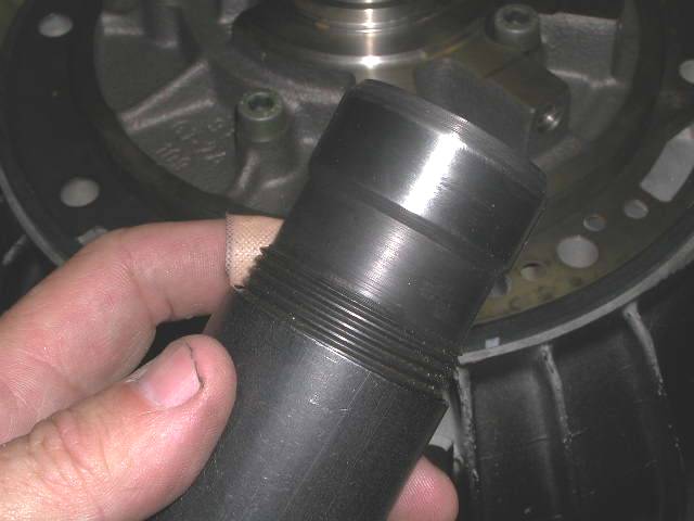
One of the last things to go back in is the low reverse servo. This is the servo that actuates the rear most band - in older Explorers it is the main cause of that 1/2 to 1 second delay in engagement when you move the shift lever from park to either R or D. What causes that is a leaky seal. FORD used an O-ring seal there. Later (and still trying to figure out it FORD did this or if it was aftermarket) a different kind of seal - a "double lipped seal" was used to help prevent leakage. (LIP seals are inherently better at sealing higher pressures than are o-rings). Maybe this is a good place to start, to look at the O ring and double lip seal:

15286DSCN5007.JPG


The difference is apparent. Here's another view..

15286DSCN5006.JPG


Most rebuild kits these days are coming with the double lipped seal. I am still trying to determine if FORD ever made them, and if so the part No. but without success so far.

Now lets look at the piston and rod assembly... there are two seals.... the big one (double lipped in our case) and a smaller one for the inner bore..

Maybe a good place to see them is in this pic....with the servo piston and rod in a vise...

15286DSCN4982.JPG


WHY in a vise you ask? Well, with some hesitation (mainly because I cannot fully comprehend what benefits it gives or why) there is a MOD to this servo that I have decided to try. I'm going to show you this MOD now, but caution you to wait and dry fit the piston all together to get a feel for the proper play in it before you take it apart. It is impossible to do once you have taken it all apart and done the MOD. SO - here is the MOD but if you are going to do it, DO THE MOD AFTER YOU CHECK PROPER PLAY with an intact servo!

The mod involves disassembly of the piston. There is a spring inside the piston you do not see. To get it apart you put it in a vise and tighten the vise until the snap ring at the end of the shaft can be removed. Snap ring? More of a circlip...

15286DSCN4984.JPG


and something of a PITA to remove. I ended up using 2 small screwdrivers. The ring will FLY when you take it off, so be careful not to send it into orbit.
Here is the stock piston apart

15286DSCN4985.JPG


It consists of the turned aluminum piston, a spring, a stepped rod and the washer on the rod (plus the absent circlip). In the mod, you replace the longish spring shown with a shorter, stronger one, and reassemble WITHOUT the circlip. Here is a pic of the new spring on the rod

15286DSCN5011.JPG


and here is the parts laid out... left of the rod are the old parts disassembled, to the right is the new MOD spring and an assembled piston assembly...

15286DSCN5010.JPG


when you assemble it using the new spring without the clip, the inner spring portion will sit slightly proud, like so..
(apologies for pic focus)

15286DSCN5013.JPG


SO, anyway that's the MOD.... BUT... before you do that (if you choose to - I am still trying to figure out exactly what it does as a benefit - if someone knows IM me and I'll include it here) be sure and use the fully assembled piston to check out our play.

GAUGING THE LOW INTERMEDIATE SERVO/BAND TRAVEL

This is a tough call for me. By gauging I discovered that I had the reverse band slip out of position and was able to maneuver it back without disassembling the transmission. Had I sinply ignored gauging I might never had found that. THEN I gauged without everything in place and came up with a number for piston travel that was NOT GOOD [piston travel should be between .120 and .220]. Bought a new sized LR assembly and THEN discovered I had gauged it wrong. Result, old one was JUST FINE. So...
how critical is this? I'm guessing not very. BUT, since I have the tools to do it, I will, and drag you along with me in the process, ok ?

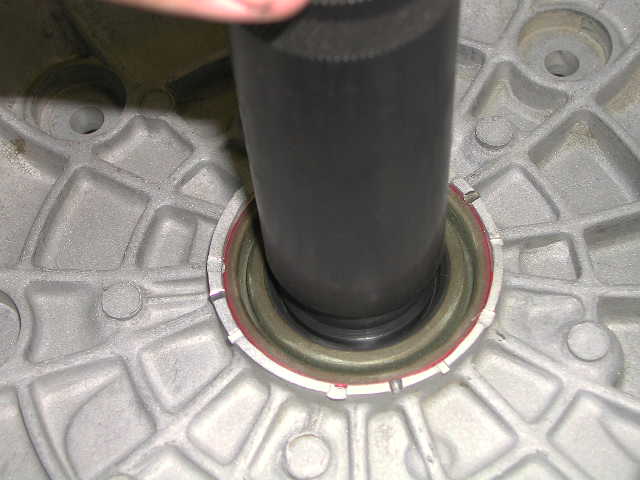
I'll need to add some pictures maybe... but... with the valve body in place, and using the gasket for the cover ... add the gauge over the installed servo piston/rod... press the servo down and tighten the screw... to a mild hand tighten (35 INCH lbs!)... add a dial indicator and zero it...

15286DSCN5008.JPG


then unscrew the bolt in the gauge and measure how far UP the piston/rod come (now you see WHY you need a unitized assembly, not a modified one)
This was one revolution plus .020... perfect... (the desired range is .120 to .220)

15286DSCN5009.JPG


Now we will add the modded rod setup ... in other words the rod, the washer and the Mod spring.. centered on the rod and washer as best we can...


15286DSCN5067.JPG


Next we'll add the piston and spring...

15286DSCN5068.JPG


which we follow with the new gasket and cap... which I have npo pic of because it takes 2 hands.... anyway piece of cake, the spring is easily overcome.... once in torque it to 90 inch lbs too... and voila you're done...


Filter

[EDIT - The filter you want to use is the one made my SPX called the microfelt filter. FRAM markets it. Unfortunately PEP Boys does not carry it, nor does AutoZone. Kragen (or the other names it uses in other parts of the country)...DOES. It is cheaper from bulkpart.com, but you need to make sure you order the o-rings and gasket. In my rebuild kit... the O-rings had to be ferreted out from the mess in the grab bag.... I have heard some sellers do not even include them.... leading to DIY errors... hence I wrote the following rant. By the way I checked a box at Kragen today - the FRAM one... it HAD the O-rings....so maybe my rant was misplaced (most are). Anyway... with that out of the way...enjoy.]

BEGINNING OF ORIGINAL POST

This is very frustrating to me. I think of the DIY errors and frustrations the filter replacement has to be high on the list. WHY? Because the mfgr's do not give you simple info you need. They sell you a filter and do not include the O-rings. Criminal. Ok rant done...Let's walk through this....

here's the filter...bottom

15286DSCN5042.JPG


and top..

15286DSCN5043.JPG


The filter essentially "plugs" into the bottom of the valve body.... in 2 holes... a BIG one...

15286DSCN4978.JPG


and a smaller one...

15286DSCN4980.JPG


the fit needs a "gasket" or in our case an O-ring... here's one on the big "plug in" portion of the filter...

15286DSCN5001.JPG


and here is one on the smaller one...you can clearly see the "microfelt" element....

15286DSCN5000.JPG


speaking of which here is a view thru the pickup....

15286DSCN4997.JPG


The early filters were but a poor screen... this filter is MUCH better... BUT... people need to know what ALL is needed.... so SAVE the O-rings off the old one and reuse them.... Oh and the attachment bolt they provide.... is too long... SO do they give us 2 bolts and instructions? NOOOO we get but a single bolt... with a funky washer/spaer on it... if you are 4WD... USE THAT washer/spacer.... (it is almost like they WANT you to mess it up, ya know? grrrr)... here is the bolt AND washer/spacer (whichever you prefer to call it)

15286DSCN4999.JPG


another view

15286DSCN5070.JPG


One last note.. lube the O-rings.. it is a tight fit and may require a little effort to seat it properly....it needs to be liquid tight.

Here it is installed...

15286DSCN5072.JPG


One word of wisdom. That pickup snout length seems to have had varied applications. Your pan should fit the pan rail easily. If it seems that something is holding it off... it is that snout! Don;t force it! It can be cut down with a hacksaw. In fact... the aftermarket cast pans require that. (So did MY pan and it's stock!)

THERE! FILTER COMPANIES PROPERLY CHASTISED! and filter installed CORRECTLY !

Gee, what's left? Electrical connections and then the PAN !


Join the Elite Explorers for $20 each year.
Elite Explorer members see no advertisements, no banner ads, no double underlined links,.
Add an avatar, upload photo attachments, and more!
.


Electrical connections

Not much was computer controlled on the A4LD... just the 3-4 shift and the Torque convertor lockup.... but still we need an electrical connection. Unless you removed your connector to tank the case, yours should still be there. I had a new case, and I did not have one so I had to move it from another case.... HOW to get it out? Well, there is a tab on the back, where you cannot see it... here are a couple side views...
this one clearly shows the tab that retains it...


15286DSCN5073.JPG


here is another view...

15286DSCN5074.JPG


The "grab bag" of seals and 0-rings has replacements for this, so I replaced them... I used a small curved sharp probe to remove them...

15286DSCN5075.JPG


you merely press it into the hole (lube the rings first) and you are set... BUT...


YOU HAVE TO DO IT BEFORE YOU PUT THE VALVE BODY IN AS THE VALVE BODY RETAINS IT TOO !

You guessed it. I put MY valve body in twice. DUH. I'll post a not above to remind poeple who took theirs out not to make MY mistake!

Ok installed we hook up the solenoids... front red (matters not which terminal is which...

15286DSCN5078.JPG


here they both are connected

15286DSCN5079.JPG


Wasn't that an electrifying performance? Done!


Back
Top