Hello everybody! It's time to start the SAS on my Explorer. It will be an awesome project and the first project of this type and size that I have ever undertaken. Up to this point the sliders where the hardest thing that I have made myself. I am open to any suggestions and or insights from anyone as the project gets underway. I have bought every last part for the build minus the hard brake lines (axles, and from master to the frame) and the flexible lines that go down to the axles. Those are all easy to make so I am not worried about it for now until I get the axles put together and can see what i want to do with those.
Now for a list of things I will be doing with the project:
1995 F-150 8.8 - I bought this used rear axle that I will strip, lock with a Detroit, convert to Explorer Disc brakes, and mount to the truck. Factory rear sway bar will be used. I will be doing a spring over conversion and will also be remaking the rear V8 anti axle wrap bars to help the leaf springs out with the leverage and TQ the V8 37's and 5.13's will put on them.
1976 F-150 HP Dana 44 - I bought this used axle and will be stripping it of the Ford factory wedges, trussing, and building custom glorified radius arms. Like DB_1 runs and like Rubicon Expresses makes. Front will also have a Detroit Truetrac LSD in it as well. This Dana 44 has 1/2" thick axle tubes.
Fox 14" Remote reservoir coil-overs - I will be building shock hoops for these coil-overs, bracing them, and tying them together across the top of the engine with removable double lock tube clamps.
1995 F-150 Steering box - This will be mounted inside the frame rail and used with the factory PS pump and will build a custom steering link from the box to the column. I picked this 1 to keep it ALL Ford and 2 because they are fairly cheap and easy and can be tapped for hydro assist at some point if I want or need it. In order to fit this steering gear I also have to remote mount my oil filter so that it has room. I will be getting rid of the factory oil cooler and have a Trans Dapt remote filter relocation kit.
Project Parts Section:
-37X13.50 R17 Interco M-16's
-Fox 14" Remote reservoir coil-overs with Eibach Springs.
-Detroit Locker for the 8.8
-Detroit Truetrac for the Dana 44
-Yukon 5.13 gears for both front and rear.
-Both axles will receive ALL new bearings races and seals u-joints etc.
-All wheel studs front and rear and spindle studs have been replaced for safety reasons. To cheap not to.
-Already had EBC brakes on it so those pads on rear will be reused and new EBC 7000 series pads for the front have been purchased.
-New front rotors wheel bearings and new Spicer ball joints, going to reuse the warn locking hubs as they work great and are in good order and easily changed later if i wanted.
-1978 Ford T-Bird calipers have been bought in place of the factory F-150 ones. They are 17% bigger in piston size so will give me a little more brake up front to help stop those 37's.
-Trans Dapt Oil filter relocation Kit and addition mount to hook to the block at a 90*.
-Currie Johnny Joints and Rubicon Express Clevite bushings for the all the link ends.
-GM 1 ton tre's for the steering with a high angle tre at the pitman arm.
-Front axle truss. (wasn't impressed with it at all so will be making some changes)
-Extending current Expedition rear drive shaft and will have a custom double cardon one made for the front.
-Metal used: 2"X.250 wall DOM for lower links, 1 1/2"X.250 wall DOM used for upper links, 1 1/2"X.375 wall DOM used for trac bar, and ALL tabs and brackets will be made out of 1/4" Flat plate by me.
-Double lock tube clamps for the shock hoop cross brace that uses 2 3/8" bolts on each. These are so It can be removed.
-All Grade 8 hardware will be used.
-All flexible brake lines will be braided stainless steel Teflon lined hoses.
I like to follow others projects and often find myself wanting more pictures so bare with me there will be A LOT of pictures of the build. I hope you enjoy lots of pictures as much as I do.
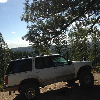
First some pictures of what the truck was! Then onto some parts pictures. Build will start shortly.
1998 XLT Explorer. 5.0L with the 4R70W trans. I have the 4406 T-Case. 3.73 gears with rear LSD. Goodyear 31's. Rock sliders and front skid plate. Links to those builds are in my signature.


And here is some video links!") There are a few videos of me wheeling in CO with nssj2!
There are a few videos of me wheeling in CO with nssj2!
Now for a list of things I will be doing with the project:
1995 F-150 8.8 - I bought this used rear axle that I will strip, lock with a Detroit, convert to Explorer Disc brakes, and mount to the truck. Factory rear sway bar will be used. I will be doing a spring over conversion and will also be remaking the rear V8 anti axle wrap bars to help the leaf springs out with the leverage and TQ the V8 37's and 5.13's will put on them.
1976 F-150 HP Dana 44 - I bought this used axle and will be stripping it of the Ford factory wedges, trussing, and building custom glorified radius arms. Like DB_1 runs and like Rubicon Expresses makes. Front will also have a Detroit Truetrac LSD in it as well. This Dana 44 has 1/2" thick axle tubes.
Fox 14" Remote reservoir coil-overs - I will be building shock hoops for these coil-overs, bracing them, and tying them together across the top of the engine with removable double lock tube clamps.
1995 F-150 Steering box - This will be mounted inside the frame rail and used with the factory PS pump and will build a custom steering link from the box to the column. I picked this 1 to keep it ALL Ford and 2 because they are fairly cheap and easy and can be tapped for hydro assist at some point if I want or need it. In order to fit this steering gear I also have to remote mount my oil filter so that it has room. I will be getting rid of the factory oil cooler and have a Trans Dapt remote filter relocation kit.
Project Parts Section:
-37X13.50 R17 Interco M-16's
-Fox 14" Remote reservoir coil-overs with Eibach Springs.
-Detroit Locker for the 8.8
-Detroit Truetrac for the Dana 44
-Yukon 5.13 gears for both front and rear.
-Both axles will receive ALL new bearings races and seals u-joints etc.
-All wheel studs front and rear and spindle studs have been replaced for safety reasons. To cheap not to.
-Already had EBC brakes on it so those pads on rear will be reused and new EBC 7000 series pads for the front have been purchased.
-New front rotors wheel bearings and new Spicer ball joints, going to reuse the warn locking hubs as they work great and are in good order and easily changed later if i wanted.
-1978 Ford T-Bird calipers have been bought in place of the factory F-150 ones. They are 17% bigger in piston size so will give me a little more brake up front to help stop those 37's.
-Trans Dapt Oil filter relocation Kit and addition mount to hook to the block at a 90*.
-Currie Johnny Joints and Rubicon Express Clevite bushings for the all the link ends.
-GM 1 ton tre's for the steering with a high angle tre at the pitman arm.
-Front axle truss. (wasn't impressed with it at all so will be making some changes)
-Extending current Expedition rear drive shaft and will have a custom double cardon one made for the front.
-Metal used: 2"X.250 wall DOM for lower links, 1 1/2"X.250 wall DOM used for upper links, 1 1/2"X.375 wall DOM used for trac bar, and ALL tabs and brackets will be made out of 1/4" Flat plate by me.
-Double lock tube clamps for the shock hoop cross brace that uses 2 3/8" bolts on each. These are so It can be removed.
-All Grade 8 hardware will be used.
-All flexible brake lines will be braided stainless steel Teflon lined hoses.
I like to follow others projects and often find myself wanting more pictures so bare with me there will be A LOT of pictures of the build. I hope you enjoy lots of pictures as much as I do.
First some pictures of what the truck was! Then onto some parts pictures. Build will start shortly.
1998 XLT Explorer. 5.0L with the 4R70W trans. I have the 4406 T-Case. 3.73 gears with rear LSD. Goodyear 31's. Rock sliders and front skid plate. Links to those builds are in my signature.
And here is some video links!
There are a few videos of me wheeling in CO with nssj2!