SOHC V6 Timing Chain Saga | Page 9 | Ford Explorer Forums - Serious Explorations

  • Register Today It's free!

SOHC V6 Timing Chain Saga

Your old pump

Dale, would you like to change that oil pump? I did mine because of the work to get down to the balance shaft. I had never driven my truck, it was wrecked, so I only started it once to listen to it for a few minutes. The pump was $90 then from Ford, and I didn't have anything in the pans. I did it back then because of the lack of knowledge about these issues, for insurance.

Don, As I recall you have about 75,000 miles on that oil pump and it is in good condition. I was planning on installing a new pump when I do the bearings, rings and head work in a year or two. Thanks for the offer! I'll keep it in mind.


Join the Elite Explorers for $20 each year.
Elite Explorer members see no advertisements, no banner ads, no double underlined links,.
Add an avatar, upload photo attachments, and more!
.


Progress & problems

I inverted the engine on the stand to make it easier to remove the reinforcement section. As I did one of the plastic pieces from the rear guide fell out of the engine to the floor. When I attempted to remove the longer Torx bolt adjacent to the rear main seal I found that my 1/4 inch drive Torx male socket was too large to fit in the slot as shown in the photo below.
BigSkt.jpg

I had to use a file to remove some burrs in the slot before the Torx socket would fit squarely on the bolt head.

As I was extracting one of the reinforcement structure perimeter bolts it fell out of the socket and into the open end of the exhaust manifold. It slid/rolled down the inclined manifold toward the exhaust port in the head. I rotated the engine 90 degrees hoping the bolt had not entered the head. Fortunately, it hadn't and I was able to fish it out with a wire.

The photo below shows the engine bottom end after removal of the reinforcement section. There is plenty of sludge on the oil pump exterior and the main caps. The rotating parts have much less build up.
MoreCrud.jpg

I'm wondering if a lot of the sludge is due to the rear main seal stopleak I had in the engine for a couple of months.

The current dilemma is how to extract the guide pieces remaining in the engine. I know that two significant pieces were located below the head and more than one inch forward of the rear of the block casting in an internal oil opening. The approximate location is marked by the arrow in the photo below.
Piece1.jpg

I tried to reach them by placing my fingers thru the rear jackshaft plug opening and the guide assembly lower mounting bolt hole but only succeeded in pushing them where I can no longer see them when looking downward thru the rear of the head casting around the camshaft sprocket. I'm hoping that the piece that fell out when I inverted the engine is one of the pieces. The chamber where the pieces are located doesn't appear to pass downward into the lower area of the crank. I don't want to try to blow them out because they'll probably just move farther forward into the interior of the engine. Even if I pull the head off, I doubt the chamber will be exposed. My current plan is to bend the end of a stiff wire into a small diameter loop and then make a right angle bend in the wire about an inch from the loop. I'll apply wheel bearing grease to the loop and see if I can catch a piece of plastic. If I stand the engine on it's rear it might fall out but that is somewhat difficult to do. Any other suggestions are welcome.


Can you see in there at all with better light? I'd be going in there with very long screw drivers to dig it out. Hopefully you can see the whole space eventually from the angles you can get with it on the stand. That seems weird to have passages that you can't get into very well.

My truck and the oil pump had 77,450 miles on it when I got it. At the time I figured to make it last another 150k or so. That rear cassette which you are working on was my biggest worry. Let me know how your looks if you get it in one place. Is it so fragile that it should be swapped sooner than the typical 150-200k people seem to run them?


SOHC block photo

The photo below by Jamieh560 is the only one of the right bank I could find on the forum after doing a search.
Picture019.jpg

In the photo it looks like the cooling jacket is between #3 cylinder and the opening for the rear timing chain components. The chamber where the plastic pieces are located may be an opening to the jackshaft enclosure. If I pull the head I'll have much better access to the chamber but that will probably be my last resort.


How about a mini hose for a shop-vac? I use an 18" piece of PVC tubing duct-taped to the crevice tool. Put a piece of stiff wire in the tubing to shape the extension.


Does help Dale?

rearblock.jpg


rearblock2.jpg


Perfect photo!

Does help Dale? . . .

That was the exactly the photo I needed! I've marked arrows on the area where the trapped pieces are located.
Chamber.jpg

You can see why I hoped inverting the engine would cause the pieces to fall out.

How about a mini hose for a shop-vac? I use an 18" piece of PVC tubing duct-taped to the crevice tool. Put a piece of stiff wire in the tubing to shape the extension.
Good idea! I don't have a shop vac but my wife's vacuum cleaner has a detachable hose with a narrow cleaning attachment. Since I can't see the pieces, I'd have to sift thru the dust bag to see what I got.


Replacing rear timing chain guide by pulling only head

I now believe that it is possible to replace the rear timing chain guide assembly by pulling the head and not pulling the engine or transmission. The guide assembly pivot bolt is not very long and not far from the top of the engine right bank. The guide assembly upper positioning bolt is attached to the head and the camshaft sprocket must be removed to remove the head. There is probably enough room to get a Torx male socket and 1/4 inch ratchet drive between the firewall and the head of the guide assembly lower pivot bolt. It may be necessary to remove some of the sound insulation at the firewall to completely extract the Torx bolt. Once the guide assembly is released it should be possible to work it out past the timing chain.

I want to emphasize, however, that it is not possible to replace the rear timing chain, or jackshaft rear sprocket without removing the flexplate or flywheel which requires either pulling the engine or the transmission.


So the rear cassette guide is removable while leaving the chain in place?


Will try to confirm

So the rear cassette guide is removable while leaving the chain in place?

I believe it is very possible with the head removed. When I purchase my new rear cassette I will try to determine if the guide assembly can be replaced with the chain attached and the head in place. It may be possible to just loosen the guide assembly pivot bolt enough by reaching between the block and firewall with the head still in place. The upper intake manifold would have to be removed for better access. It all depends on if there is enough width in the rear of the block casting for the combined width of the chain and guide assembly. The life of the chains and sprockets greatly exceed the life of the guides. It would certainly be nice if the rear guide assembly could be replaced by just removing the upper intake manifold and the right valve cover.


Must separate engine & trans to replace rear guide

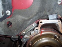
After closer examination I have decided that the engine or transmission must be pulled in order to replace the rear timing chain guide assembly. It is not possible when just removing the engine head. The bolt for the guide assembly pivot is within the bellhousing and not accessible from the outside without separating the engine from the transmission. The red arrow in the photo below identifies the location of the guide assembly pivot bolt. The green arrow identifies the location of one of the transmission to engine bolts. The blue arrow identifies the stain left by a very thin metal plate that is mounted between the transmission and the engine.
GuideBolt.jpg

If the engine head is removed, the guide assembly bolt shaft will be visible thru the block casting but the bolt head will not be accessible. It is not possible to grasp the shaft with locking pliers to unscrew the bolt because a transmission to engine bolt is above and in the way of the guide bolt. The photo below by shelbygt shows the area of interest at the rear of the block.
rearblock.jpg

The green arrow I added identifies the casting that receives the transmission to engine bolt. The red arrow identifies the barely visible guide assembly bolt below the casting.
The red arrows in the photo below identify the location of the guide assembly pivot bolt.
 

Attachments

  • TransLoc.jpg
    TransLoc.jpg
    47.2 KB · Views: 3,695


Crankshaft journal & bearing

I decided to inspect the condition of the crankshaft journal and bearing farthest from the oil pump. The photo below shows the #1 crankshaft journal that appears to be in fairly decent condition after 10 years and 150,000 miles.
CJrnl1.jpg

The photo below shows the mating #1 bearing and cap.
BCap1.jpg

The red arrows in the photo below shows plastigauge on the #1 crankshaft journal after torquing and removing the original bearing and cap.
PlstiGag.jpg

The width of the plastigauge indicates a clearance of .003 inches. I repeated the plastigauge test near the bottom of the journal next to the oil hole and the indicated clearance was slightly less than .002 inches. I believe that the bearings will last for another 10,000 miles.


This is the perfect time to go thru this engine. I know you say you only want to do the timing chains but I know you're probably tempted to dive into it. The sludge in that engine is incredible. What do the cylinders look like?


Yes, I'm tempted

This is the perfect time to go thru this engine. I know you say you only want to do the timing chains but I know you're probably tempted to dive into it. The sludge in that engine is incredible. What do the cylinders look like?

You're correct that the deeper I get the more tempted I am to do the rebuild now rather than later. However, I need some time to consider various potential improvements, to find sources for needed parts and acquire them, and to identify a local desirable machine shop.

I don't plan to pull the heads so I don't know what the top of the cylinders look like. I haven't checked the lower parts for the pistons near the top.


Rear guide assembly

The wheel bearing grease on the wire loop did not work because the grease wouldn't stick to the oily guide fragments. I was able to use two stiff wires )one thru the head and the other thru the jackshaft rear plug opening) to remove the two large fragments trapped in the chamber. The photo of the larger pieces of the rear guide assembly shown below illustrates why I would like to eliminate the traction side of the guide and it's positioning post.
RCasset.jpg

The slack side of the guide assembly is in good condition with less than one tenth of the depth of the chain contact surface worn away by the chain. The slack side could easily last for another 500,000 miles from a wear standpoint. The wear on the traction side of the guide assembly is comparable to the slack side and the depth of the remaining chain contact surface is about the same. The traction side cause of failure was structural possibly from physical stress, vibration, heat or a combination of all three. I suspect the reason the timing chains break is because a large piece of guide fragment gets wedged between the moving chain and some stationary item such as the block. If the plastic had been bonded to a metal backing in a manner similar to the way brake material is bonded to a brake shoe the guide would still be intact.

The red arrow in the photo identifies the worn head of the positioning post that was ground off by the slapping chain. The green and blue arrows indentify potential large pieces that I have not recovered. The black arrow identifies the guide assembly pivot bolt.

I was under the impression that the rear guide assembly had not been revised. However, the photo below of a later one shows that I was mistaken.
RtUpr.jpg

The slack side of the guide in the photo appears to be constructed of a metal reinforced plastic chain contact material. While this in my opinion is an improvement, it will not prevent the failure I experienced on the traction side.
I will determine if eliminating the traction guide and compressing the upper tensioner more will allow enough slack to shorten the chain one link. If so, then I'll discuss doing so with a machine shop. If the idea proves feasible, then I'll reuse the slack side section of my old guide and evaluate how it does between now and the future engine rebuild.


StreetRod, is the slack side of the old guide made entirely of plastic, or does it have some metal backing?

I know the front guide has been re-designed mant times, and in fact there have been four different part numbers for it. IRRC the 97 and 98 SOHC engines had front cassettes that were 100% plastic


Entirely plastic

StreetRod, is the slack side of the old guide made entirely of plastic, or does it have some metal backing?

I know the front guide has been re-designed mant times, and in fact there have been four different part numbers for it. IRRC the 97 and 98 SOHC engines had front cassettes that were 100% plastic

My 2000 guide assembly is entirely plastic except for the metal bushing that used to hold the traction and the slack sides together at the pivot point. Since the traction side that enclosed the bushing broke off there was excessive clearance at the pivot and the slack side was at an angle but still between the upper tensioner and chain. However, when the engine wasn't running the chain was so loose on the traction side that I could almost lift it off the camshaft sprocket even though I had just installed a new tensioner.


Join the Elite Explorers for $20 each year.
Elite Explorer members see no advertisements, no banner ads, no double underlined links,.
Add an avatar, upload photo attachments, and more!
.


Also, did you find the new tensioner much stronger than the old one, or were they similar?


Back
Top