Chief Tons of new mods!!! Good Ones!!!! | Page 3 | Ford Explorer Forums - Serious Explorations

  • Register Today It's free!

Chief Tons of new mods!!! Good Ones!!!!

Hello Everyone,
Long time no talk..... Anyway, I have been doing some work. A Lot! I will list in Chronilogical order how this has come about. Then I will Start with the first mod and try to make some nice contributions here for all. Dont worry, detailed reports will come as I report on each Item... There is sort of a lot of explaining........

1) Re-design Radiator support. (finished)
-To Allow for More clearance between engine and for rubber Isolator
mounting
-Re- Paint Rad Support.
2) Fabricate custom Aluminum Radiator shroud. ( Finished )
-Purchase and install Flex-A-Lite Fan Variable Speed Controller.
-Purchase and install DUAL Spal High- Performance 13" Fans.
3) Modify Ron Davis Radiator. (Finished)
-To Allow For remote filler neck
-To Allow for mounting of new shroud.
4)Fabricate New Front Crossmember. (Finished)
-To Eliminate Frame Flexing
5)Rebuild T-5 Tranny with High Alloy gears ( Finished)
-So It Wont Break Again!!
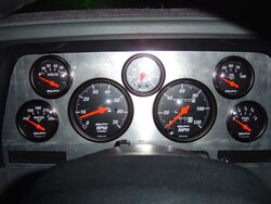
6)Fab.Gauge Pod for New"factory style" intrument cluster. (Finished)
7)Install Full Autometer Phantom II gauge set.(Went With Sport Comp)
8)INSTALL KENNE BELL 2.2 BLOWZILLA!!(Coming Soon)
-More power to handle new gear ratios
-Also, ...... ITS MORE FUN!!!

I know that is alot to take in....... I will try to post as I can On the work I already have "(Finished)" and What I am in process with as it happens.\

Yes I will have pics as usuall.... Because otherwise this thread will suck :rolleyes: I know you will have tons of questions, bring em on... But dont get ahead of ourselves (ie; what about the blower??!) as keeping up will be alot of work to begin with. We dont want to make this a mixed up thread that noone can get usefull info out of.

I will try to get pics and info up Wednesday 13th in the late evening!! Talk to you soon!
-Chief


Join the Elite Explorers for $20 each year.
Elite Explorer members see no advertisements, no banner ads, no double underlined links,.
Add an avatar, upload photo attachments, and more!
.


here are some more, sorry for the glare in a couple

P.S. Notice that BOOST guage right in the middle?? ;)

The last pic kinda sucks because the panel is not mounted yet and it was sliding down a little.. You can see it when you look at the rectangular cutout for the stock indicator lights. Anyway when it is pushed back and mounted the rectangle will match that hole perfectly......
 

Attachments

  • gauges temp installed close up.JPG
    gauges temp installed close up.JPG
    60.8 KB · Views: 401
  • Gauges temp installed pass profile.JPG
    Gauges temp installed pass profile.JPG
    60.3 KB · Views: 394


Join the Elite Explorers for $20 each year.
Elite Explorer members see no advertisements, no banner ads, no double underlined links,.
Add an avatar, upload photo attachments, and more!
.


So the next part of this write up will include pictures and will show how I make the speedo cable work, and wire up the gauges with all the new sending units. I will also finish the install with mounting and painting of the new panel. then we will have a finished product. Keep your panties on I will be working on it tomorrow, with any luck I will get it finished!! Talk to you soon...

Feel free to ask any questions. I will try to answer.
-Tim

P.S. Matt I know you probably want to see it in person, let me know.... call me and cruise by to check it out. :D


Thanks alot Froader.....

I finally finished it tonight. I have been super busy lately. anyway, I finished wiring everything up tonight and everything was working great! I had to take the panel back out and paint it. So tomorrow I will put the gauges back on the panel and hook it all up for real. I will get the rest of the pictures on here with the rest of the write up. Turned out to be a bit of a chore but It was well worth it.

Talk to you guys tomorrow hopefully....


Lookin pimp as usual. How long till a supercharged 5.0 just isn't big enough for you?? :D I give you.. 8 months. :p:


I have a question about the electric fan you installed. Do you think it would be possible pulling the fan off without a puller? Also performance wise did you notice any differance? I am trying to pick up a lil more power in my x and just trying to figure what to do on a budget.


Hi,
I finished everything tonight.... I got pics but I am to tired to get it on here right now. I will finish the write-up tmorrow.

Section 525,
Thanks for the props, wait till you see the finished product. It came out even better than I could have expected! Heh and as for the 5.0 supercharged, Well I will be tackling that next and I hope I can hold out a little while but I do want a 347 supercharged ;)

Pgdsm,
I assume you are talking about the stock 4.0 fan and fan clutch.... You dont need a puller to get them off. The issue is getting to the NUT that holds the fan clutch onto the water pump pulley. they make a special wrench that helps alot. It is basically just a skinny wrench. Anyway, It can be done with a pair of channel locks. I did it plenty of times . I think I had to remove a couple of the bolts from the water pump pulley in order to fit the channel locks down in there to get to the fan clutch nut. Anyway, The electric fan will help alot. It makes the engine sound much cleaner because you dont hear the loud air noise from the stock fan. Also, You will notice a big difference in responsiveness to the throttle. The truck will accelerate quicker and I believe you will be happy. I know I was.....

talk to ya tomorrow......


Nice Job cant wait to see the rest of the pics


This is looking really nice.


ok next was to take the panel with gauges back out and finish up.


The next obstacle was to deal with the speedo cable. On the back side of the white gauge pod is a circuit board. It is flexible. The are very thin flat copper "wires" going through the circuitry and it is laminated . I had to go through and follow the "wires" around and make sure I could make a hole in it for the speedo cable without disrupting anything I needed to keep. here is a pic of it.
 

Attachments

  • back of gauge pod.JPG
    back of gauge pod.JPG
    60 KB · Views: 334


So it turns out I was going through part of the circuits for the dash lighting which would disrupt the turn signals if interupted. So I had to cut thruough the circuits and solder jumper wires back in to reconnect the circuit.
 

Attachments

  • close look at circuit mod before.JPG
    close look at circuit mod before.JPG
    59.7 KB · Views: 327
  • circuit board cut and folded back.JPG
    circuit board cut and folded back.JPG
    57.9 KB · Views: 321
  • jumper wires on circuit board.JPG
    jumper wires on circuit board.JPG
    60.4 KB · Views: 323
  • another shot of the jumper wires.JPG
    another shot of the jumper wires.JPG
    61.3 KB · Views: 332


This was fairly difficult because the flat copper circuits are extremely thin and they are laminaterd. So I had to slice the lamination of with a razor blade and be super carefull soldering the wires to the circuits because to much heat and it would just melt the copper away. Anyway after 4 connections and folding the flap out of the way, I widened the existing hole a little bit for the speedo cable.

I had a place called San Diego Speedo and Tach make a new speedo cable for me. They used my stock sensor of my existing cable so it would fit back into my transfer case and put a 5/8" 18 thread female end on the other so it would hook up to the Auto meter gauge. I also had them make it 8" longer to give some room to work. This was 55 dollars. Well worth it!


Now that that was taken care of.... I mounted the white pod back in the dash and started running some wiring.... I tapped of of the dash lighting wiring already in the dash to get power for the gauge lights. one main wire crimped onto an end with Seven, 18 gauge red wires with but connectors for power to the lights. I ran a Main Ground wire from the back of the engine, where the battery ground hooks to it into the dash area and crimped on an end with 13 grounds...... 7 for lighting and 6 for gauges. I then tapped into a line under the dash that was an ignition feed for an ignition source for the gauges. this was crimped on to an end with more power wires to slpit toward the gauges.......
 

Attachments

  • Gauge wiring coming out of firewall.JPG
    Gauge wiring coming out of firewall.JPG
    61.6 KB · Views: 337
  • New wiring for gauges.JPG
    New wiring for gauges.JPG
    60.5 KB · Views: 318
  • Another shot gauge pod new wiring.JPG
    Another shot gauge pod new wiring.JPG
    60.2 KB · Views: 334


Oh yeah I also brought in a few "signal wires as well for the gauges. One for the oil pressure sending unit. One for the new water temp sending unit and one tapped off the negative coil wire for the tachometer..... I will do the boost , and fuel gauge during the blower install..... here is the new water temp sensor with wiring.... It was just a matter of replacing the old one with the new one.....
 

Attachments

  • water temp sending unit.JPG
    water temp sending unit.JPG
    58.8 KB · Views: 319


The oil pressure sending unit was a little more complicated.... The new unit is about 4 times larger than the stock unit. I needed to make room. I unscrewed the existing stock "extension adapter". This screws into the block and the sending unit screws into the end of it. It is about 4.5" long or so. Anyway I cut the very end off where the sending unit screws into it. I then shortened about 1.5" or so and my freind welded the end back on. It was very easy and only took a few minutes. This shortened the assembly up a little so the new sending unit would clear the power steering pump ...... Look closely you can see the weld.....
 

Attachments

  • oil press sending unit new one.JPG
    oil press sending unit new one.JPG
    59.1 KB · Views: 308
  • Shortened oil sending unit extension housing.JPG
    Shortened oil sending unit extension housing.JPG
    59.6 KB · Views: 315


And Finally...... Here is the piece after it has been painted and riveted in. I will paint the rivet heads with a small brush later.........
 

Attachments

  • new gauges pass side further away.JPG
    new gauges pass side further away.JPG
    59.8 KB · Views: 300
  • new guages foront pass side.JPG
    new guages foront pass side.JPG
    60.7 KB · Views: 312
  • new gauges front driver side.JPG
    new gauges front driver side.JPG
    59.6 KB · Views: 309
  • best shot new gauges front.JPG
    best shot new gauges front.JPG
    59.5 KB · Views: 323


By the way the radio doesent really look blue like in the pic......

Here it is lighted!! Sorry pic doesent look to good buut the gauges look awesome..... I am pleased to say the least!
 

Attachments

  • New guages front lighted.JPG
    New guages front lighted.JPG
    57.9 KB · Views: 305
  • new gauges front driver side lighted.JPG
    new gauges front driver side lighted.JPG
    58.5 KB · Views: 310


Dude that rocks!


Join the Elite Explorers for $20 each year.
Elite Explorer members see no advertisements, no banner ads, no double underlined links,.
Add an avatar, upload photo attachments, and more!
.


Back
Top