Something w/ rabbits. 72.5 pages of BS | Page 51 | Ford Explorer Forums - Serious Explorations

  • Register Today It's free!

Something w/ rabbits. 72.5 pages of BS

So seeing as spring is just around the corner, I thought I'd start a thread on the future undertaking of swapping in the Dana 60.

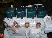
The axle is from a 1986 "Fawwd" F-threee "fitty", sporting some kingpins and a whole lot of rust. I took this axle apart a few months ago (except stupid me didnt remove the pinion nut before breakdown :rolleyes:) and had it hot tanked. I wanted it sandblasted, but the machine shop owner smirked and said "naaah yo, that junx is too big for my blasting cabinet" .. okay except he didn't really say that cauz he's old and a really cool guy. ANyways *twirls blonde hair*, this is my plaannn:

- WMS-WMS this axle is just a bit over 69" wide so I'm going to cut the passenger's side down a few inches to match 'ye ol General Motors 14-bolt axle. So this is going to require custom axle shafts and I think I'm going to go Chromos and 35-spline outers off the bat from the most awesome guys at Complete Off Road.

- Drive flange or lockouts? They are about the same in price and its a dedicated trail rig so I'm leaning towards the drive flanges. Right now, the cheapest flanges I found are the Teraflexes at $180 for a pair. If anyone knows of a better deal, please let me know :D !!

- High-steer arms and a double-ended hydroponics goodness ("cylinder").

- Opposite-ended panhard bar! The idea is to mount the chassis end of the panhard on the passenger's side frame rail and the axle end on the driver's side. Doing so should allow a more simple and cleaner design since the axle-mount can be mounted on top of or near the differential housing, instead of a tower on the passenger's side (like in my current D44 setup). I also plan to boost the panhard as far up as possible to increase the roll center of the front suspension. Yeah the concept is a little strange but I'm hoping it'll work and won't have any issues (no drag-link to factor into the design). But if anyone knows of any problem running this config, please chime in!

*EDIT*
- Detoit Locker for the carrier. I'm please with how the Detroit in the 14-bolt has performed so I figured I'd run the same in the front. Of course 5.13s to match the 14-bolt.


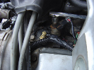
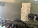
So here's the little guy, he's been in this position for the past few months just collecting dust:

DSC000871.jpg


Join the Elite Explorers for $20 each year.
Elite Explorer members see no advertisements, no banner ads, no double underlined links,.
Add an avatar, upload photo attachments, and more!
.


Join the Elite Explorers for $20 each year.
Elite Explorer members see no advertisements, no banner ads, no double underlined links,.
Add an avatar, upload photo attachments, and more!
.


What is the advantage of welding them in? I use them but just slide them in as the heim goes in.
flexed013.jpg


From a non-racing point of view, I guess there are not that many advantages but I weld them in so I dont loose them.

But if we were racing and lives depended on it, I would weld them in because the weakest point of a bolt is at the "root" of the thread - that is the area at the end of the thread of the bolt closest to the head. If the thread's root happeend to be at or near the mount, then welding the spacers in would help significantly as the shear area is no longer at the root of the bolt.


Well I didnt do a very good job explaining soo....

Colors:
Blue = mount
Green = spacer
Pink = heim

shear.gif


In figure A, we see that the weakest section of the bolt (again, its the "root") is also the same section where the heim is applying a shear force (red arrow on the right) because the spacer is not fixed and therefore, one possible situation is that the spacer moves with the heim. If the bolt were to snap, I would bet that it will snap in that red area.

However, in figure B where the spacers have been welded, the shear force is only where the heim and the spacers meet and therefore, the setup is slightly stronger than figure A because the weakest section of the bolt is not in the section of the bolt where shear forces are being applied. Therefore, the force required to snap this bolt in figure B from the force being applied by the heim will probably be greater than the force required to snap the bolt in figure A.

Again this probably doesnt really matter in our world because were not really running that fine line between weight and strength like in Formula 1 or whatever. Usually, we just overbuild and that is more than enough for most of us because two more pounds of steel (in heims and bolts) is nothing in our world.


A good book with more info about fasteners as they apply to race cars than anyone could ever care for is "Engineer to Win: Understanding Race Car Dynamics":
engineer_to_win.jpg

Reviewed here: http://www.explorerforum.com/reviewpost/showproduct.php/product/362/cat/500


Are you still making all those holes with a hole saw?


That I am

seafarer76 - I think I'm pretty much done but the IG LED on the Stim stays lit all the time no matter what RPM the engine is at or position of the TPS. I followed the instruction for EDIS so is this correct?


The IGN led should be pulsing. You may not see the pulses, but you should see it brighten or dim by RPM (I think, I am using GM HEI, which works differently). Did you set the settings in Megatune?

In MegaTune, set:

Trigger offset = 0° (this will vary, depending on the wheel/pickup configuration),
Ignition Input Capture to 'Rising Edge', ('Falling Edge' for MicroSquirt® only if using the VR input circuit - not recommmended),
Cranking Trigger to 'Calculated',
Coil Charging Scheme to 'EDIS',
Spark Output to 'Going High (Inverted)', ('Going High (Inverted)' for MicroSquirt).
Trigger Wheel Teeth to '0' (zero)

Set the predictor algorithm option to 'last interval'.


Thanks seafarer76 - but not go.

I also checked over all the hardware settings on the EDIS page and everything checked out okay.
http://www.megamanual.com/ms2/EDIS.htm
V3.0 main board:
use the 'Hall sensor circuit' (step #50.a in the assembly guide) - jumper D1 and D2,
jumper OPTOIN to TACHSELECT on the bottom side of the PCB, near the DB37 connector, opposite the heat sink,
jumper TSEL to OPTOUT on the bottom side of the PCB, near the center.
jumper JS10 to IGN (this uses the processor port for the SAW signal directly),
jumper XG1 to XG2 on the bottom side of the PCB, near the 40 pin socket,


From a non-racing point of view, I guess there are not that many advantages but I weld them in so I dont loose them.

But if we were racing and lives depended on it, I would weld them in because the weakest point of a bolt is at the "root" of the thread - that is the area at the end of the thread of the bolt closest to the head. If the thread's root happeend to be at or near the mount, then welding the spacers in would help significantly as the shear area is no longer at the root of the bolt.

I understood just fine, thanks for the pointer!!


Do you line bore the holes after you weld the spacers on? I'm just asking because we usually have to when we do this for hydraulic cylinder mounts because the holes tend to shrink when welded.


Do you line bore the holes after you weld the spacers on? I'm just asking because we usually have to when we do this for hydraulic cylinder mounts because the holes tend to shrink when welded.
When I drill and after the the bit has gone through, I usually loosen the table and move the piece just a little bit to enlarge the diameter by a hair. For the panhard bar mount on the chassis end, since they were small enough to fit in the drill press, I did clamp them onto the drill press' table and redrilled them after welding. For the parts that are too big for the drill press, then I just go at it with an abbrasive drill attachment to enlarge it just by a hair - usually thats enough to let the bolt go through with little effort.


If you have access to an Oscilloscope, you can probe pin 36 and see if you are getting a square wave output. Barring that, if everything else checks out, you can hook it up and run it. If the MS is not sending out the correct SAW pulses, then you will have a fixed 10 degree advance. If the ignition advances smoothly, then your MS is putting out the correct pulses.


I dont have access to an oscilloscope right now but pin 36 goes to the "IG" LED after passing through R13 on the Stim. I put a voltmeter across R13 (easiest to access with the multimeter) and as I change the RPM pot, there is a voltage difference (of about 0.6v) from 0 RPM to whatever the max is - but its a steady continuous voltage, no fluctiation as one would expect if a square wave was going through.

EDIT: In the video below, from 24 seconds till the end, the RPM is at about 360 which should be low enough to blink the "IG" LED, but nope :(


Can you probe from pin 26 to pin 36? What is the voltage across the two pins at 0rpm, 500 rpm and 5000 rpm?

Can't watch the vid until tonight (work)


The voltages across 26 and 36 are:
  • 0 RPM - 3.34v
  • ~500 RPM - 3.20v
  • ~5000 RPM - 2.64v

Thanks for all the help so far seafarer76!!


Sounds like its working to me...


Sounds like its working to me...
Okay thanks.

I guess the next step in verifying it is to connect an EDIS unit with at least one spark plug. I'll try that later on in the week or the weekend.

Thanks again seafarer76 - you've been a great helP!


You'll also have to have the 36-1 wheel input to the EDIS.

Bite the bullet and fire the engine..... :cool:


Join the Elite Explorers for $20 each year.
Elite Explorer members see no advertisements, no banner ads, no double underlined links,.
Add an avatar, upload photo attachments, and more!
.


Are you still making all those holes with a hole saw?
Iz, you better smooth out those holes so no one cuts their fingers off. You know how everyone likes to feel a piece of fabricated steel..........or am I the only one???:p: (Did I just say that out loud?)


Back
Top