SOHC V6 Timing Chain Saga | Page 11 | Ford Explorer Forums - Serious Explorations

  • Register Today It's free!

SOHC V6 Timing Chain Saga

Chain mod may not be possible

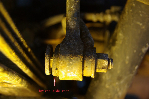
I spoke with an automotive machinist today about the possibility of removing one link from my rear timing chain. He's been doing custom engine rebuilding for many years and was not at all encouraging. He said if it was a roller chain that I would have a much better chance than with the type of chain that Ford is using. The original chain was manufactured in Italy. The front and rear chains with sprockets are shown in the photo below. I compared the lengths of the two chains in hopes that the front was shorter but it is identical to the rear. If one link was removed it would only shorter the total length about 0.75 inches. I think it might fit without the traction side of the guide assembly and less lateral deflection on the slack side but I'm not going to remove a link to find out unless I can find some way to reliably attach the two ends.

On another subject, I am uncertain which way the jackshaft front camshaft chain sprocket should face. Does the smooth face of the sprocket face away (as shown in the photo) or toward the block? I haven't been able to find any photo of the jackshaft camshaft chain sprocket without the jackshaft primary chain sprocket in the way.
FrtNRr.jpg


Join the Elite Explorers for $20 each year.
Elite Explorer members see no advertisements, no banner ads, no double underlined links,.
Add an avatar, upload photo attachments, and more!
.


Here Dale, I re-sized this and put it in my project file. In one picture I can read the word ITALY on the links. I don't recall the gear being different on ether side, I can see the number 04 on this.
 

Attachments

  • Projectthread067.JPG
    Projectthread067.JPG
    109.4 KB · Views: 5,631


Here Dale, I re-sized this and put it in my project file. In one picture I can read the word ITALY on the links. I don't recall the gear being different on ether side, I can see the number 04 on this.

By looking at the picture posted by CDW6212, it looks as if Ford had no choice but to build the guides with deflection on the traction side. It looks as if the path the chain follows is curved and not straight. If these guides have lated for 150,000 miles, I expect the new improved guides should last even longer.

StreetRod, have you removed the front left guide? What condition was it in?


Another perfect photo!

Here Dale, I re-sized this and put it in my project file. In one picture I can read the word ITALY on the links. I don't recall the gear being different on ether side, I can see the number 04 on this.

Thanks Don. That's exactly what I needed! There's a recessed area near the center on the back side of the sprocket probably to mate with the jackshaft. I guess I would have been able to figure it out upon reassembly but I like to be certain.


Very good. You have already noted that the crank pulley goes on with the dots on the back? My early pictures of my thread show it backwards, I hope it doesn't confuse anyone. Don't flip it so the dots are visible, the balancer will end up out 1/8" or so. I learned that the hard way.

These are the front and rear of the crank gear.
 

Attachments

  • CrankgearFront.JPG
    CrankgearFront.JPG
    24.5 KB · Views: 3,690
  • CrankgearRear.JPG
    CrankgearRear.JPG
    26.1 KB · Views: 3,660


Front guide assembly wear

By looking at the picture posted by CDW6212, it looks as if Ford had no choice but to build the guides with deflection on the traction side. It looks as if the path the chain follows is curved and not straight. If these guides have lated for 150,000 miles, I expect the new improved guides should last even longer.

StreetRod, have you removed the front left guide? What condition was it in?

The traction side is on the exhaust (outer) side of the head for the front cassette. There is very little curve to it as shown in the photo below.
LftGuide.jpg

Since it is fairly straight, as the guide chain contact material wears the relative timing between the jackshaft and the camshaft does not change.

The slack side is the side where the hydraulic tensioner contacts the guide and keeps the slack side of the chain from slapping.

My front guide assembly was in excellent condition until I broke off the small, curved bottom piece of the traction side trying to remove it from the head. The main reason I decided to replace it was my fear that the all plastic assembly would structurally fail into fragments like the rear assembly did. As you can see in the photo, the new one is a metal structure with attached chain contact material. Unfortunately, the plastic is not bonded to the metal. It is attached with plastic friction latches. I will possibly separate (very carefully) the plastic from the metal and reassemble the pieces with epoxy glue. My only concern is the different coefficients of expansion for metal vs plastic.


I got my heads on today and timed the cams.
I ran into 2 problems. One is neither of the new Ford tensioner for the heads have washers. When I removed mine, the front one had on and the rear did not. Aside from possibly leaking, I don't know what issues I would have from not installing a washer on the rear.

The second problem was when tightening the rear cam sprocket bolt, I assumed that my torque wrench would "click" in reverse when I reached the right amount of 63ft lb. I know I went way passed that before I realized it (like a dummy). So I removed the bolt and checked for any damage and then re torqued it with a bar type torque wrench. This bolt is not torque to yield, but Ford thought enough of it to put in in the kit, so I hope it will be ok. Might it be a good idea to put the old bolt back in.... in case the new one was weakened from over torquing?

On the instructions that came with the jackshaft kit, it tells you to attach the "tools" and then to rotate the cams until the slots line up with the one side of the tool. Problem is, you can not rotate the cams once the tool is attached. Unless I am missing something, it didn't make sense. What I did was.... remove the upper sprocket and chain, put in the old bolt and rotated the cams with a breaker bar and socket to where they needed to be then attached the tool with that fits into the slot and then attached the chain and sprocket together and finally the tool to hold the sprocket...then torqued the bolt.

I now need yet another tool for the upper oil pan (BIG hex socket) to torque the reinforcements that butt up on the main caps. :(


motortimed.jpg


motortimed2.jpg


A few problems

I got my heads on today and timed the cams.
I ran into 2 problems. One is neither of the new Ford tensioner for the heads have washers. When I removed mine, the front one had on and the rear did not. Aside from possibly leaking, I don't know what issues I would have from not installing a washer on the rear.

My stock configuration was the same as yours. I suggest you install the rear tensioner without the compression ring. The oil pressure port on the tensioner is very close to its hex head inner face as shown in the photo below.
RtTnsCls.jpg

The thickness of the compression ring might partially block the port. I would torque to 49 lb-ft.

The second problem was when tightening the rear cam sprocket bolt, I assumed that my torque wrench would "click" in reverse when I reached the right amount of 63ft lb. I know I went way passed that before I realized it (like a dummy). So I removed the bolt and checked for any damage and then re torqued it with a bar type torque wrench. This bolt is not torque to yield, but Ford thought enough of it to put in in the kit, so I hope it will be ok. Might it be a good idea to put the old bolt back in.... in case the new one was weakened from over torquing?

Did you use special tool 6485 included in your kit to torque the rear camshaft bolt? If so, did you over torque the 45 lb-ft or 63 lb-ft specified? The special tool extends the lever arm amplifying the torque applied by the torque wrench. If you used the tool and over torqued the 63 lb-ft on the wrench then the bolt was actually torqued to more than 88 lb-ft. If that's the case I would reuse the original bolt. Otherwise, other members have torqued the camshaft bolt more than specified to avoid the possibility of it slipping and have not reported any problems. The grade of the bolt is not marked on the head but I suspect it to be a high quality bolt. I wouldn't worry about it.

On the instructions that came with the jackshaft kit, it tells you to attach the "tools" and then to rotate the cams until the slots line up with the one side of the tool. Problem is, you can not rotate the cams once the tool is attached. Unless I am missing something, it didn't make sense. What I did was.... remove the upper sprocket and chain, put in the old bolt and rotated the cams with a breaker bar and socket to where they needed to be then attached the tool with that fits into the slot and then attached the chain and sprocket together and finally the tool to hold the sprocket...then torqued the bolt.

What you did sounds correct.

I now need yet another tool for the upper oil pan (BIG hex socket) to torque the reinforcements that butt up on the main caps. . .

My Haynes manual emphasizes backing out those hex head inserts before attaching the lower reinforcing structure to make sure they don't bind on the top of the main cap bolts. It shows loosening them with an allen wrench and then instructs to torque them to 12 ft-lb on installation. That's hard to do with an allen wrench. To do it right a set of hex head sockets are needed. I assume that they are metric. Looks like another trip to Harbor Freight and a $15 purchase.
98229.gif


Did you replace your front/timing cover seal? I never removed mine when removing the front cover and the primary timing chain instructions don't mention replacing it.

Yeah I replaced the seal, figured might was well.

On the hex bit for the oil pan reinforcement. I bought the metric set from Harbor Freight and of course the 10mm was too small and the 12 mm is too big. It is either an 11 or the SAE equivalent.
Be forewarned, the only place that had the correct size was Advance Auto Parts and you have to buy the entire 46.00 kit for the right one. So I bought a set from Autozone with a 12mm and I am going to grind it to fit. I can't wait another week for a tool to get this thing back together! Going on a month now of downtime. The unforeseen hurdles make me CRAZY!


I have a PDF document for assembly instructions if you need it.

Pm your address and I'll send it to you.


Too late but thanks

. . . On the hex bit for the oil pan reinforcement. I bought the metric set from Harbor Freight and of course the 10mm was too small and the 12 mm is too big. It is either an 11 or the SAE equivalent. . .

I knew I should have checked the required size before buying the set from Harbor Freight. Oh well, it was only $10 and might come in handy in the future. I have a set of metric allen wrenches so I may just estimate the torque if I have the correct size. I doubt that the torque is critical since the inserts are only spacers.


I knew I should have checked the required size before buying the set from Harbor Freight. Oh well, it was only $10 and might come in handy in the future. I have a set of metric allen wrenches so I may just estimate the torque if I have the correct size. I doubt that the torque is critical since the inserts are only spacers.

Dale, if I had found a set of allen wrenches with the correct size I would have done that too, but I struck out at 3 parts stores, Sears, K-Mart, and Harbor Freight. I just got done grinding and it worked! It's not pretty, but it worked. I had to go back over the inserts 5 times in sequence, I guess because it was only 12 ft lbs, so each time they loosened up by about half.

Now I have a question if anyone has the torque specs for the inner crankshaft reinforcement section bolts (8 of them) My Haynes manual says 10-12 "INCH" lbs then 23-26. At 26 I can grab the socket and remove the bolts....this can't be right! I know these things were a heck of a lot tighter that this when I removed them. Anyone have the Ford specs, or maybe a Chiltons?
Thanks!!


I have a PDF document for assembly instructions if you need it.

Pm your address and I'll send it to you.

Jakee, I have the Haynes manual and the Ford instructions for the jackshaft kit replacement, which one did you have??


That 12lbsft of torque is like a trans pan bolt. You should be able to do that by hand, it's basically wrist tight. Without a torque wrench on it, the allen wrench, use the short end if it fits and use only your wrist. That's not much torque, but you should be able to do it well enough, instead of buying a special socket set or ordering one, or grinding on another.


That 12lbsft of torque is like a trans pan bolt. You should be able to do that by hand, it's basically wrist tight. Without a torque wrench on it, the allen wrench, use the short end if it fits and use only your wrist. That's not much torque, but you should be able to do it well enough, instead of buying a special socket set or ordering one, or grinding on another.

The problem was nobody has sells them larger than 10mm. The 12 ft lbs was actually tighter than I thought it would be. Like I said when sequencing the inserts, they loosened up a little and you can't really sense or judge that with an Allen wrench. However, I think as long as they are tight against the mains, it should be fine.

Dale I saw that and I guess it didn't register to my brain, since I know the book says ft lbs unless specified. .. :D That makes sense now! Thanks for the wake-up call. :p:


Jakee, I have the Haynes manual and the Ford instructions for the jackshaft kit replacement, which one did you have??

I just sent it too two different people so maybe they'll post it up for you. If not, I'll sent it to you if you pm your address. It's fords assembly instructions for the 2005 4.0 SOHC Mustang. The core part of the mustang engine is pretty much the same as ours with the most recent updates.


Join the Elite Explorers for $20 each year.
Elite Explorer members see no advertisements, no banner ads, no double underlined links,.
Add an avatar, upload photo attachments, and more!
.


Thanks!

I just sent it too two different people so maybe they'll post it up for you. If not, I'll sent it to you if you pm your address. It's fords assembly instructions for the 2005 4.0 SOHC Mustang. The core part of the mustang engine is pretty much the same as ours with the most recent updates.

I received and briefly reviewed the document. It will be extremely helpful. Thank you very much Jake!


Back
Top