LD50 Full-size axle thread `93 Ex | Page 13 | Ford Explorer Forums - Serious Explorations

  • Register Today It's free!

LD50 Full-size axle thread `93 Ex

LD50 Full-size axle thread `93 Ex SAS

Hey fellow Explorer enthusiasts!

Well I never thought I`d do it, but it`s time.
I originally thought I would go to a smaller rig one day but I`m going to beef up the Explorer instead. Since I already have a huge thread on my previous work I decided to start fresh.

If you would like to see my previous mods, you can navigate from my signature link, or click here:
http://www.explorerforum.com/forums/showthread.php?p=523171#post523171

~

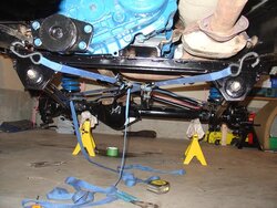
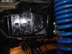
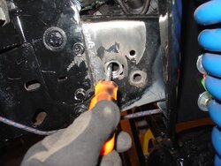
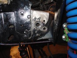
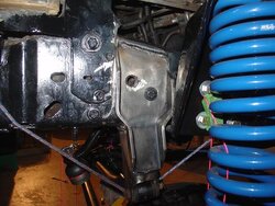
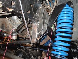
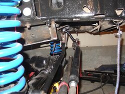
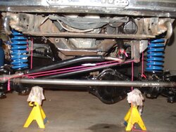
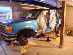
My plans are to install a D44 and 9-inch into the station wagon and run 35 inch tires. Hopefully she`ll still get in the garage, but if it don`t then oh well. During this I also have some body work to do.

Right now I have the rear end out, I took off the spare tire hanger and removed the muffler and rear most heat shield. (doors are off for body work)Next the gas tank comes out so I can prep the underside for rust protection, from the t-case back. In the meantime I am trying to sell some parts for cash.

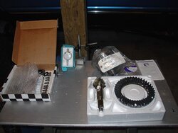
First big decision is what gear ratio. The 4.10`s on 33s was nice, but I think I`d like a bit more torque than that so I`m thinking 4.88 or 5.13s.
 

Attachments

  • prep.JPG
    prep.JPG
    62.9 KB · Views: 10,440


Join the Elite Explorers for $20 each year.
Elite Explorer members see no advertisements, no banner ads, no double underlined links,.
Add an avatar, upload photo attachments, and more!
.


Actually I`ve never done it, I just imagine it would be easy. If you calculate strength compared to leveraging ability over a sick ***** in a sitting position, pulling one off a toilet should be a snap.
:p:

I'll keep that in mind if I see a sick *****, I'll try it and let you know.


Join the Elite Explorers for $20 each year.
Elite Explorer members see no advertisements, no banner ads, no double underlined links,.
Add an avatar, upload photo attachments, and more!
.


Actually I`ve never done it, I just imagine it would be easy. If you calculate strength compared to leveraging ability over a sick ***** in a sitting position, pulling one off a toilet should be a snap.
:p:

Along with calculating :scratch: suspension geometry Ld50 is a whiz at "Sick *****" theorems :D


ID- I like your drag link bend. I did mine like that too. It kept my joint near level at ride height so it had plenty of down and up travel.


I have to apologize..
Due to the traditionally "slumped over" position of sick ****** on toilet seats, Their center of gravity (COG) is already so far off center that it actually resides outside their bodies. Typically this slumped over position is maintained by the propping up of their off-center mass with elbows resting on their legs a few inches from their knees.
It would be harder of course, to pull one straight forward than it would be to pull them to the side.
If taken by surprise, pulled quickly by the hair and to the side, I calculate you could topple one with as little as 5.9309626 Newtons of force OR about 3/4 lbf.

Perhaps I exaggerated a little, it was not quite that easy to get that pitman arm off.

:D


Kirby, yeah, that method does seem to make sense.

Anyway, I had the machine shop shorten my trac-bar for me. It was shortened 3.5 inches for a new mount center to center length of 32 3/4 inches.

I am figuring my angle here for my bracket for the frame side of the trac-bar.

(PS, I forgot about the phenomenon that occurs when you turn your wheel with the engine off. your power steering pump lid will blow off and shoot power steering fluid everywhere. That is the fluid you might see in the pics)

Now, I am using string to get the correct angle figured out (about 12.5*)
Thing is, it might be confusing as to where to find the angle on my drag-link.
I tied one end to the grease nipple and the other end I tied so that it is centered at about half the TRE, where I figure the pivot point would be.
I don`t see a more accurate way to do it, if someone has a better idea I`m all ears.
 

Attachments

  • trac and drag angles 1.JPG
    trac and drag angles 1.JPG
    58.8 KB · Views: 777
  • trac and drag angles 2.JPG
    trac and drag angles 2.JPG
    58.2 KB · Views: 782


Thats the best way to do it! Thats how I did mine


The only downside of a bend in the trackbar is that you have to do a full rotation of adjustment every time. But it just determines how centered the wheel is so whatever. It does make full use of the travel available which is important IF you've got flex. ;)

Your string method makes sense to me. :thumbsup:


Yeah, the trackbar is a little bit of a pain for assembly, but once it is set it shouldn`t be too much trouble.

Today I just spent a little time double checking my axle alignment. It of course crucial to the other measurements, and I,ve measured and re-measured it to the point of anality throughout all this setup.

Using my tie down straps help with the fine adjustment, I notice over time they slacken and my centering loses only 1/8 inch or so either way.

The best way to measure for center is to measure from points you know are true. I did find points that would work okay once I discovered them, but for true accuracy I measured from the inside of each shock tower, to the inner edge of the lower coil seat, using a plumb-bob. (My floor is even, that is important)

When I just did it, I was only out by maybe a 16th of an inch.
 

Attachments

  • final axle centering 1.JPG
    final axle centering 1.JPG
    77.6 KB · Views: 785
  • final axle centering 2.JPG
    final axle centering 2.JPG
    49.9 KB · Views: 745
  • final axle centering 3.JPG
    final axle centering 3.JPG
    45.5 KB · Views: 762
  • final axle centering 4.JPG
    final axle centering 4.JPG
    69.3 KB · Views: 784


The only downside of a bend in the trackbar is that you have to do a full rotation of adjustment every time. But it just determines how centered the wheel is so whatever. It does make full use of the travel available which is important IF you've got flex. ;)

Your string method makes sense to me. :thumbsup:

This is true. Mine is bent such that I can still adjust it with out taking it off. Also, I can do fine adjustment by taking one joint off and giving it a turn- or a half a turn with heims which works out as half or quarter as much as a full turn of both. Mine had enough flex that even with the bend it would take my heims from one misalignment to the other.


You and i think alike, as ive still got the two ratchet straps and plumb bobs on mine right now. :D I ran the 'bobs off of each outside of the frame, and measure from them to the radius arm wedge. You are right about the straps stretching.


trackbar bracket SAS

Pretty unique to how much lift you have as to how to build your bracket, but here`s what I did..

I cut about 5.5 inches from mount holes up, off the stock F150 bracket, and built mine off of that. There is a wierd angle on the frame and your steering box bolts to work around. I found where it was even, then welded a piece of angled metal to the F150 piece. After that, the bracket is a straight shot.
 

Attachments

  • f150 stock trac bar mount cut.JPG
    f150 stock trac bar mount cut.JPG
    43 KB · Views: 731


I`m only welding the top edge and under the frame where the stock F150 piece rests. As added redundancy I`m putting a nut inside the frame to bolt a big bolt too, should give me more than enough strength.

There was a stock hole in the frame, I widened it with a hand file on each side just enough to fit the bolt in..

(I trimmed a little off the ABS module mount for more room. I was going to just get rid of it altogether, but decided it could make a good conversation piece.)
 

Attachments

  • nut 2.JPG
    nut 2.JPG
    51.2 KB · Views: 735
  • nut 1.JPG
    nut 1.JPG
    56.6 KB · Views: 732


Then I used an angle pic to guide it inside without dropping it and to hold it in place before welding it there. The frame is totally boxed in at this area, so it was my only option..
 

Attachments

  • nut 3.JPG
    nut 3.JPG
    58.5 KB · Views: 742
  • nut 4.JPG
    nut 4.JPG
    64.5 KB · Views: 732


The other bolt there is one of the steering box bolts. Still need to run a tap through the nut since I got a little bit of spatter into it, but I was ready to check my measurements one last time before I welded it in place..
 

Attachments

  • tracbar bracket 1.JPG
    tracbar bracket 1.JPG
    69.1 KB · Views: 747
  • tracbar bracket 2.JPG
    tracbar bracket 2.JPG
    83.8 KB · Views: 717
  • tracbar bracket 3.JPG
    tracbar bracket 3.JPG
    72 KB · Views: 740


Just gotta paint her up, put that bolt in and she`s done!
Nice to have it finally off the list.
Next I`m going to go ahead and install my lockers and gears into the 44. I have enough info to do a good write up, so check it out!


How far forward did you end up moving your axle forward? Looks real good


Nice job as always!


Steering geometry theory lesson

Forgot to mention/reinforce the theory behind the geometry of the linkage on the solid axle, Alot might know it but some might not.

1) Your draglink (rod from steering box/pitman arm), should be the same length as your trackbar (panhard bar)

2) Your draglink and trackbar should follow the same angle.
When figuring your angle and length, it is the mounting points that determine everything, regardless of any bends in your links. (My draglink is bent and so is my trackbar.)

When these two objectives are met, your axle can move freely up and down as your suspension cycles, with your trackbar and draglink always moving as one.
If you are off, your tracbar and draglink can bind against each other, sending the resulting forces in the only direction that will allow any movement. Since your trackbar is hard mounted at both ends, the force is transmitted to your steering linkages, causing bump-steer, excessive wear of components, and possibly even tears of sorrow, because you spent all that time and money and now it rides like crap.

As shown earlier I used string lines to eyeball my angles, and shortened my trackbar to draglink length only after I ensured my axle was centered, my steering was centered, and my alignment was as close as I could get it. I didn`t want to end up with a whole bunch of neccessary adjustments to my linkages, which would make my draglink longer or shorter. I tried for perfection, but will add that exact length takes a backseat to exact angle.
 

Attachments

  • solid axle linkage alignment.JPG
    solid axle linkage alignment.JPG
    62.4 KB · Views: 729


Join the Elite Explorers for $20 each year.
Elite Explorer members see no advertisements, no banner ads, no double underlined links,.
Add an avatar, upload photo attachments, and more!
.


D44 gear and locker install

-Detroit full carrier locker
-5.13 gears
-install kit
-dial indicator with magnetic base
 

Attachments

  • D44 gear and locker install 1.JPG
    D44 gear and locker install 1.JPG
    46.2 KB · Views: 695


Back
Top